Split air conditioner for ship

A split-type, air-conditioning technology, which is applied in air-conditioning systems, hull ventilation/heating/cooling, applications, etc. It can solve the problems of low heating capacity, condensation at the air outlet, and icing of outdoor unit condensers. Effects of condensate discharge capacity, stable heating capacity, and strong corrosion resistance

Inactive Publication Date: 2014-06-11
CSIC TIANHE MARINE EQUIP JIANGSU CO LTD
View PDF6 Cites 3 Cited by
  • Summary
  • Abstract
  • Description
  • Claims
  • Application Information

AI Technical Summary

Problems solved by technology

[0003] When the ship is sailing at sea, the conventionally equipped air conditioners have been exposed to harsh environments such as salt spray and mold for a long time, and the heat exchangers of the indoor and outdoor units will be strongly corroded, resulting in a decrease in the efficiency of the air conditioner, and even a breakdown, which seriously affects the lives of the crew. , production; if the ship encounters waves that cause the hull to shake, the condensed water generated by the conventionally equipped indoor unit will overflow from the water pan when it is cooled, and the sea is a high-humidity environment. Condensation is prone to occur at the tuyere, which deteriorates the hygienic conditions of the cabin; when heating is required in winter, the working mode of the conventionally equipped air conditioner is heat pump heating, and the electric heating is auxiliary heating. Low temperature or even below minus 20 degrees will cause the condenser of the outdoor unit to freeze, resulting in a serious drop in the heating efficiency of the heat pump, while the heating capacity of the auxiliary electric heating is small and cannot meet the use requirements, resulting in the cabin temperature not meeting the normal life and work requirements of the crew

Method used


Image

  • Split air conditioner for ship

Examples


Embodiment Construction

[0014] Below in conjunction with accompanying drawing, the specific embodiment of the present invention is described in further detail:

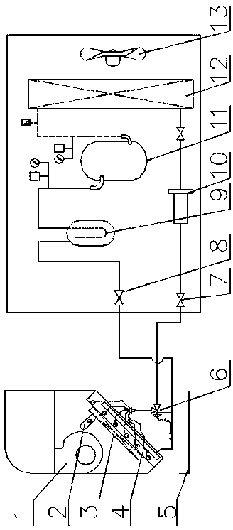
[0015] Such as figure 1 As shown, a split-type air conditioner for ships includes two parts: an indoor unit and an outdoor unit. The indoor unit includes a centrifugal fan 1, a temperature control switch 2, a heater 3, an evaporator 4, a water pan 5 and an expansion valve 6. The evaporator 4 is a copper finned evaporator, a water pan 5 is arranged directly below the evaporator 4, a heater 3 is installed on the top surface of the evaporator, and a temperature control switch 2 is arranged on the heater. A centrifugal fan 1 is provided above the evaporator; the outdoor unit includes a liquid supply stop valve 7, a fluorine stop valve 8, a gas-liquid separator 9, a dry filter 10, a compressor 11, a condenser 12, a spiral fan 13, and copper fins. The chip condenser 12 is arranged in the shell of the outdoor unit near the air outlet. The li...


PUM


Abstract

The invention provides a split air conditioner for a ship. The split air conditioner comprises an indoor unit and an outdoor unit, wherein the indoor unit comprises a water containing disc, a centrifugal fan, an evaporator and an expansion valve, wherein the expansion valve is arranged under the evaporator and is connected with the evaporator, the water containing disc is arranged right under the evaporator, the centrifugal fan is arranged above the evaporator, a heater with a temperature control switch is arranged on the upper top surface of the evaporator of the indoor unit, the outdoor unit comprises a compressor, an axial flow fan, a condenser and a drying filter, the condenser is arranged in a position near the air outlet and in a casing of the outdoor unit, the axial flow fan is arranged between the condenser and the air outlet, an outlet of the compressor is connected with an inlet of the condenser, an outlet of the condenser is sequentially connected with the evaporator of the indoor unit through the drying filter, a liquid supply cut-off valve and the expansion valve, and the evaporator is sequentially connected with an inlet of the compressor sequentially through a fluorine cut-off valve and a gas-liquid separator. Through the optimization on the fin materials and the air conditioner structure, the service life of the air conditioner is prolonged, and the split air conditioner is suitable for being used in various kinds of severe environment.

Description

technical field [0001] The invention relates to an air conditioner for ships, in particular to a split air conditioner for ships. Background technique [0002] At present, the split wall-mounted machines that are often equipped on ships are similar to household wall-mounted heat pumps to adjust the air temperature and humidity in the cabin. The temperature difference should not be too large. [0003] When the ship is sailing at sea, the conventionally equipped air conditioners have been exposed to harsh environments such as salt spray and mold for a long time, and the heat exchangers of the indoor and outdoor units will be strongly corroded, resulting in a decrease in the efficiency of the air conditioner, and even a breakdown, which seriously affects the lives of the crew. , production; if the ship encounters waves that cause the hull to shake, the condensed water generated by the conventionally equipped indoor unit will overflow from the water pan when it is cooled,...

Claims


Application Information

Patent Timeline
Patent Type & Authority Applications(China)
IPC IPC(8): F24F1/00F28F21/08F24F13/22F24F13/30F24D13/00B63J2/02
Inventor 花军曹杨健戴伟郁斌袁超
Owner CSIC TIANHE MARINE EQUIP JIANGSU CO LTD
Why Eureka
Try Eureka