Multi-layer loop multi-flame hole flameless ceramic burner and using method thereof

A ceramic burner and burner technology, applied to blast furnace parts, furnaces, heating furnaces, etc., can solve the problems of uneven air distribution in the regenerator, affecting the heat exchange effect of the regenerator, and affecting the structural strength of the fire wall in the combustion chamber, etc. , to achieve the effect of large thermal load adjustment range

Active Publication Date: 2015-10-28
WUHAN UNIV OF SCI & TECH
View PDF5 Cites 0 Cited by
  • Summary
  • Abstract
  • Description
  • Claims
  • Application Information

AI Technical Summary

Problems solved by technology

In the center of the rotary recirculation zone (in the center of the regenerator), the flue gas flow rate is very low or negative, while at the periphery of the rotary recirculation zone, the air velocity is high, which will affect the heat exchange effect of the regenerator
[0007] The Chinese patent "Multi-Fire Holes Flameless Ceramic Burner" (Patent No. 200510018640.6) discloses a burner that borrows from and improves the Kalukin-style ceramic burner, and does not form a swirl zone after the fuel and air are sprayed out , to overcome the problem of uneven air distribution in the regenerator caused by the Kalukin type ceramic burner
However, this kind of ceramic burner is arranged in a single layer on the top-fired hot blast stove, and the combustion heat load of the hot blast stove should not be too large, otherwise the design of the combustion nozzle will be large, which will not only affect the structural strength of the fire wall of the combustion chamber, but also affect the combustion of gas Effects and Flame Shapes
[0008] The burner technology disclosed above, with the expansion of the construction scale of the current top-fired hot blast stove, these burner technologies can no longer meet the requirements of the newly built large top-fired hot blast stove, so innovatively develop new burners to adapt to large top-fired hot blast stoves The requirements for combustion-type hot blast stoves have become a top priority

Method used


Image

  • Multi-layer loop multi-flame hole flameless ceramic burner and using method thereof
  • Multi-layer loop multi-flame hole flameless ceramic burner and using method thereof
  • Multi-layer loop multi-flame hole flameless ceramic burner and using method thereof

Examples


Embodiment 1

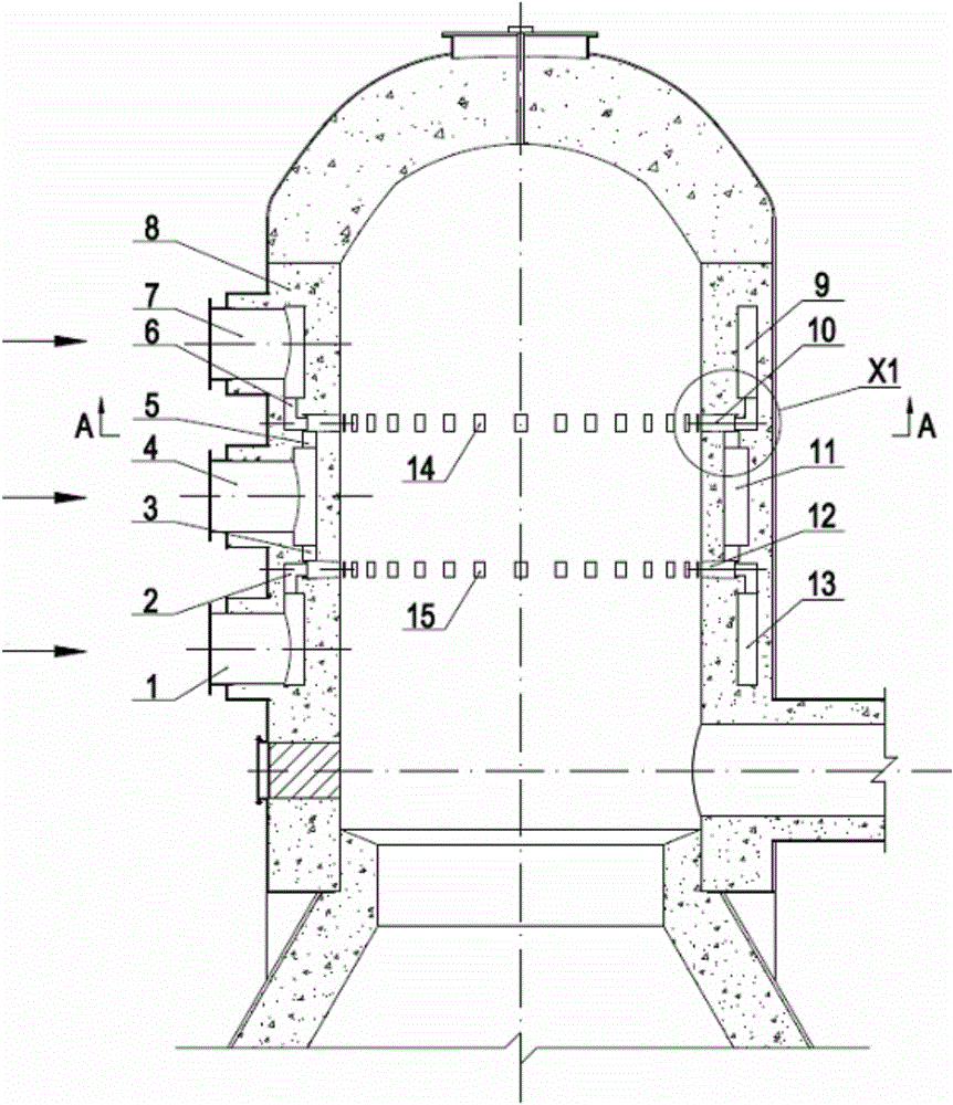
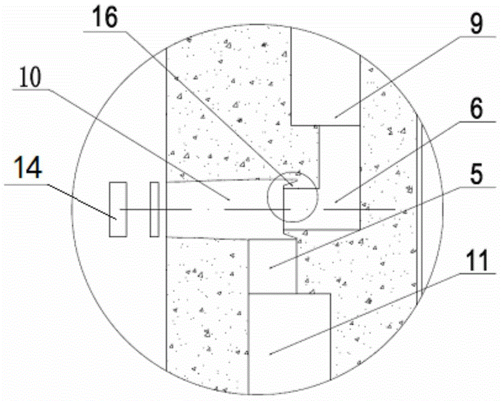
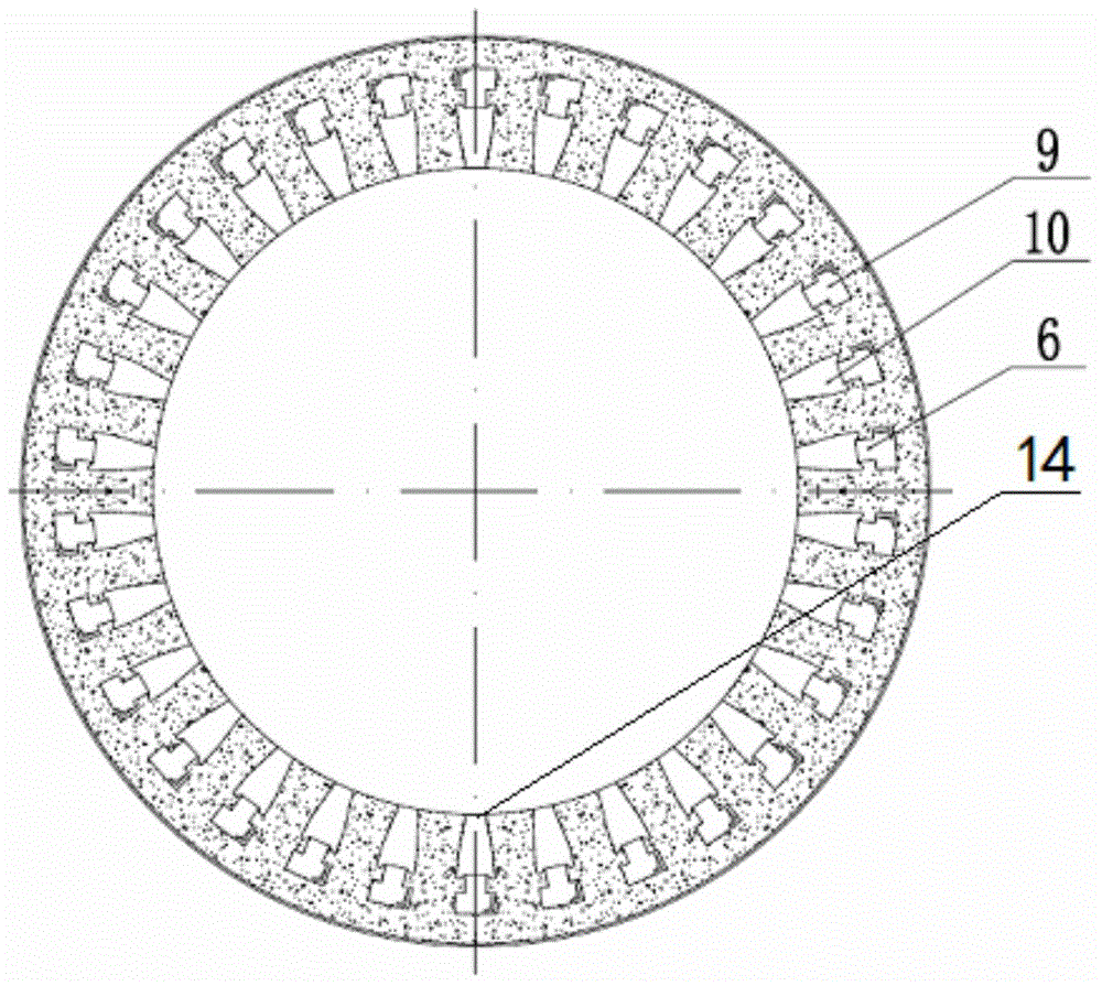
[0031] Example 1: The present invention provides a single-set multi-layer ring multi-fire hole flameless ceramic burner with a structure such as figure 1 , 2 As shown in 3, the present invention is based on the existing burner with two air inlets, two layers of annular channels, one layer of mixing channels, and one layer of combustion zone structure, in each set of flameless ceramic burners. An air inlet, a layer of annular channels, a layer of mixing channels and a layer of combustion zone with multiple fire holes are added to form a flameless ceramic burner with three air inlets, a multilayer ring and multiple fire holes.

[0032] See figure 1 , The three air inlets are respectively the lower gas inlet 1 and the upper gas inlet 7 provided in the burner. An intermediate air inlet 4 is provided between the two gas inlets. The burner is used for top combustion hot air The furnace burns blast furnace gas. Since the gas flow rate is greater than the air flow rate, the amount of air ...

Embodiment 2

[0038] Example 2: The present invention provides a single-set multi-layer ring multi-fire hole flameless ceramic burner, see Figure 4 Its structure is basically the same as that of Embodiment 1, except that the air inlet and channel are interchanged with the gas inlet and channel. The lower air inlet 17 is connected to the lower air ring, and the upper air inlet 19 is connected to the air The upper ring is connected, the gas inlet 18 is connected with the gas ring, and the gas ring is designed to have a different size from the upper air ring and the lower air ring according to needs, and the upper gas nozzle and the lower gas nozzle in the gas ring The size is also different to ensure that the gas has different air and gas distribution ratios in the upper fire hole layer and the lower fire hole layer.

Embodiment 3

[0039] Example 3: The present invention provides a method of using 3 sets of multi-layer ring multi-fire hole flameless ceramic burners in combination. Its structure is that each set of burners are arranged in order from top to bottom. The air and gas of each set of burners Corresponding to have independent air inlets, but each set of burners contains multi-layer loops, mixing channels and fire holes of different sizes.

[0040] The control of the entire combustion system for the combination of 3 sets is: each set of burners are arranged up and down between the loops and fire hole layers, and the combustion heat load and combustion air distribution between the fire hole layers in the burner are in accordance with Scale setting. For the combustion load distribution ratio, the combustion load decreases sequentially from top to bottom, that is, the amount of gas burned in the upper fire hole layer accounts for a larger proportion of the total gas, and the amount of gas burned in the...


PUM


Abstract

The invention relates to a multi-layer circuit and multi-burner port flameless ceramic burner. 1-3 sets of burners are combined and installed at the upper part of a top combustion stove when the multi-layer circuit and multi-burner port flameless ceramic burner is used; an upper gas circuit, a middle air circuit and a lower gas circuit, which are sequentially communicated with an upper gas inlet, a middle air inlet and a lower gas inlet are distributed inside the stove wall from top to bottom; an upper burner port layer and a lower burner port layer are arranged on the inner wall of the stove wall; burner port rings are evenly distributed; gas nozzles are respectively formed in the lower part of the upper gas circuit and the upper part of the lower gas circuit; air nozzles are respectively formed at the top side and the bottom side of the middle air circuit; the air and the gas respectively enter upper and lower mixed channels inside respective circuits through corresponding nozzles, and then eject through the burner ports to burn. Control of the burner is as follows: combustion heat load distribution from an upper burner port layer to a lower burner port layer is sequentially reduced, and the excessive coefficients of combustion air are sequentially increased. The air and gas inlets of the burner and the circuits are interconvertible in position, and the multi-layer circuit and multi-burner port flameless ceramic burner is applicable to various top combustion stoves.

Description

Technical field [0001] The invention relates to a multilayer ring multi-fire hole flameless ceramic burner and a method of use thereof, in particular to a flameless combustion multi-ring ceramic burner of a top-fired hot blast stove for ironmaking blast furnaces and a method of use thereof, belonging to The technical field of ceramic burners for industrial furnaces. Background technique [0002] Top-fired hot blast stoves are also called non-combustion chamber hot blast stoves. This kind of hot blast stove does not have a special combustion chamber, but uses the space on the top of the furnace as the combustion chamber. The top space of the stove is as large as the external and internal combustion hot blast stoves. The combustion chamber is much smaller. Because the top combustion hot blast stove fully absorbs the technical advantages of other types of hot blast stoves, it has been considered as the development direction of hot blast stove technology. Since the top-fired hot bl...

Claims


Application Information

Patent Timeline
Patent Type & Authority Patents(China)
IPC IPC(8): C21B9/10
Inventor 戴方钦许学成张发辉郭悦潘妮
Owner WUHAN UNIV OF SCI & TECH
Why Eureka
Try Eureka