Vacuum evaporation device
A technology of vacuum coating and evaporation, which is applied in vacuum evaporation coating, sputtering coating, ion implantation coating and other directions, can solve the problem of high requirements on mask accuracy, difficult mask production, and evaporation mask. The problem of high board production cost, to achieve the effect of reducing the manufacturing cost
- Summary
- Abstract
- Description
- Claims
- Application Information
AI Technical Summary
Problems solved by technology
Method used
Image

Examples
Embodiment 1
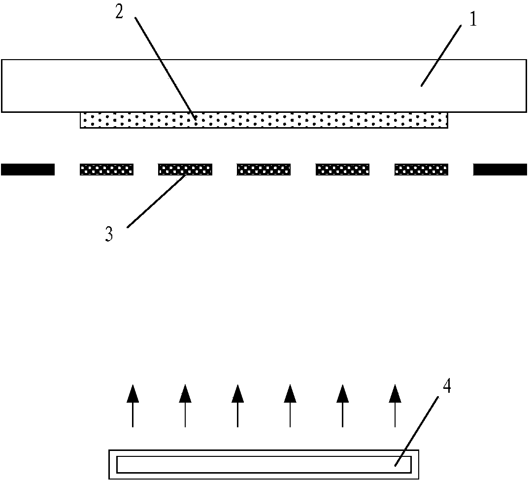
[0076] Figure 4 It is a schematic diagram of the cross-sectional structure of the vacuum evaporation device in the second direction X in Example 1 of the present invention.
[0077] Such as Figure 4 As shown, in this embodiment, the vacuum evaporation device includes:
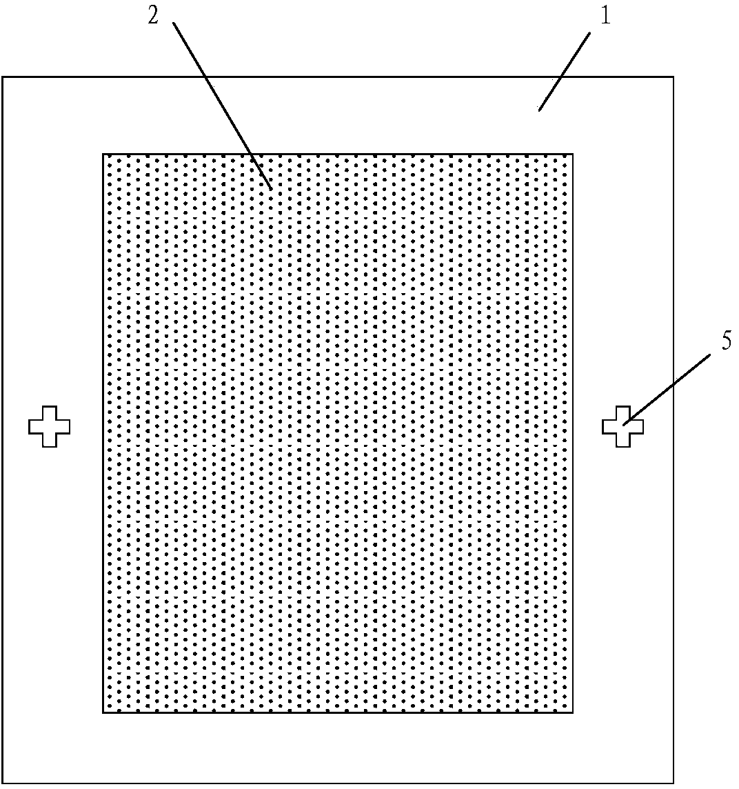
[0078] A substrate driving mechanism (not shown) for moving and carrying the substrate 100, the surface of the substrate 100 forms a pattern area 101 to be evaporated;
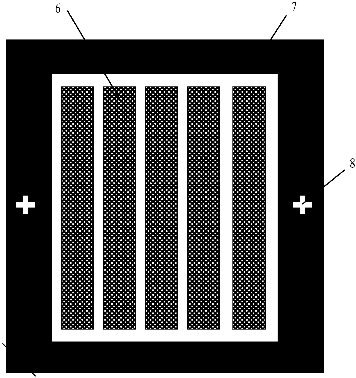
[0079] A first mask drive mechanism (not shown) for moving and carrying the first mask 201;
[0080] A second mask driving mechanism (not shown) for moving and carrying the second mask 202;
[0081] an alignment mechanism for aligning the first mask plate 201 and the second mask plate 202 with the substrate 100 respectively; and an evaporation source 300 located on the second mask plate 200 Below the mask plate 202; wherein, the size of the effective mask pattern area A formed after the first mask plate 201 and the second mask plate 202 o...
Embodiment 2
[0094] Figure 11 It is a schematic cross-sectional structure diagram of the vacuum evaporation device in the second direction X in Example 2 of the present invention; Figure 12 It is a schematic diagram of the side structure of the vacuum evaporation device in the first direction Y in Example 2 of the present invention.
[0095] refer to Figure 11 and Figure 12 , in this embodiment, the vacuum evaporation device includes:
[0096] Line evaporation source 300;
[0097] A substrate driving mechanism (not shown) for moving and carrying the substrate 100. The surface of the substrate 100 forms a pattern area 101 to be evaporated, and the pattern area 101 to be evaporated is divided into several evaporation sub-areas 1012 of the same size;
[0098] A first mask drive mechanism (not shown) for moving and carrying the first mask 201;
[0099] A second mask drive mechanism (not shown) for moving and carrying the second mask 202, wherein the first mask 201 and the second mask ...
Embodiment 3
[0119] The schematic cross-sectional structure schematic diagram of the vacuum evaporation device of embodiment 3 in the second direction X is the same as the schematic cross-sectional structural schematic diagram of the vacuum evaporation device of embodiment 2 in the second direction X; Figure 15 It is a schematic diagram of the side structure in the first direction Y of the vacuum evaporation device according to Embodiment 3 of the present invention.
[0120] refer to Figure 11 and Figure 15 , in this embodiment, the vacuum evaporation device includes:
[0121] Line evaporation source 300;
[0122] A substrate driving mechanism (not shown) for moving and carrying the substrate 100. The surface of the substrate 100 forms a pattern area 101 to be evaporated, and the pattern area 101 to be evaporated is divided into several evaporation sub-areas 1012 of the same size;
[0123] A first mask drive mechanism (not shown) for moving and carrying the first mask 201;
[0124] ...
PUM
 Abstract
Description
Claims
Application Information
 - R&D
- Intellectual Property
- Life Sciences
- Materials
- Tech Scout
- Unparalleled Data Quality
- Higher Quality Content
- 60% Fewer Hallucinations
Browse by: Latest US Patents, China's latest patents, Technical Efficacy Thesaurus, Application Domain, Technology Topic, Popular Technical Reports.
© 2025 PatSnap. All rights reserved.Legal|Privacy policy|Modern Slavery Act Transparency Statement|Sitemap|About US| Contact US: help@patsnap.com