Video surveillance method and device
A technology of video surveillance and monitoring equipment, applied in the field of communication, can solve the problems of poor flexibility of video surveillance, and achieve the effect of solving the relatively poor flexibility and improving flexibility.
- Summary
- Abstract
- Description
- Claims
- Application Information
AI Technical Summary
Problems solved by technology
Method used
Image

Examples
Embodiment 1
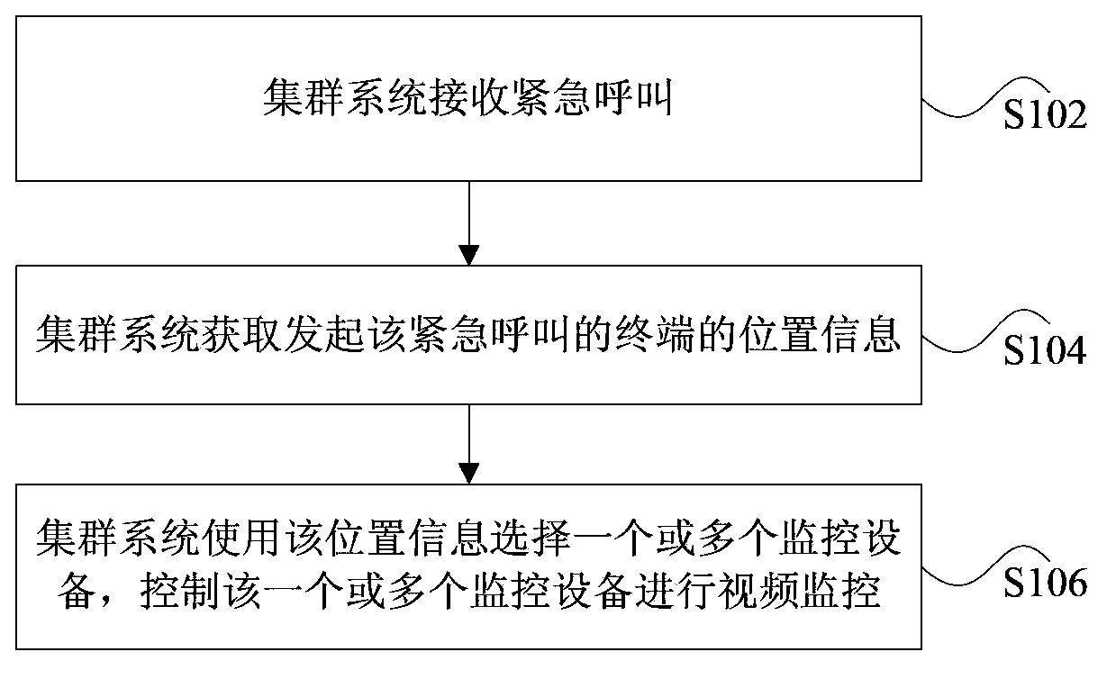
[0052] This embodiment provides a video monitoring method. In this embodiment, when an emergency call occurs, the system automatically selects N cameras (N configurable) closest to the user's location (configurable) according to the location information obtained by the user's location to initiate an emergency call. Video monitoring, so that the real-time picture taken by each camera will be presented on the main video page. At the same time, video surveillance is initiated on the camera closest to the user on the positioning main page, and then the real-time picture taken by the camera is presented on the positioning main page. A detailed description will be given below in conjunction with the following steps S202 to S12.
[0053] Step S202: The terminal initiates or raises an emergency call, and reports the emergency call status to the system side.
[0054] Step S204: The dispatching station receives the emergency call message, which is to be processed.
[0055] Step S206: ...
Embodiment 2
[0062] This embodiment provides a video monitoring system, Figure 4 is a schematic diagram of a cluster positioning video surveillance system according to an embodiment of the present invention, such as Figure 4 As shown, the system includes: a detailed description is given below.
[0063] MS41: trunking terminal, which can support storage of user information, group information, scheduling area judgment, and response to traditional group paging and other trunking services; the terminal must support positioning services and obtain its own latitude and longitude information.
[0064] BSS42: Base station subsystem, including a transceiver (BTS) that supports trunking calls, a base station controller (BSC) and a dispatch client (PDC) that interacts with the network side.
[0065] PDS43: Dispatching server, realizing call control and talk right management of trunking calls.
[0066] DAS44: Dispatch station server, which provides login service for dispatch station clients, is re...
Embodiment 3
[0073] This preferred embodiment provides a video surveillance method, Figure 5 It is a flow chart of emergency call initiator or lifter automatic video monitoring according to an embodiment of the present invention, such as Figure 5 As shown, the method includes the following steps S502 to S522.
[0074] Step S502: The terminal initiates or raises an emergency call, and the emergency call message sends a request to the PDS through the base station.
[0075] Step S504: After initiating the emergency call or elevating the emergency call successfully, the PDS sends an emergency call notification message to the DAS, and the DAS reports the notification message to the DAC.
[0076] Step S506: DAC receives the user's emergency call to be processed message, immediately and automatically initiates a positioning request to the user after processing, and the positioning request is sent to LA through DAS.
[0077]Step S508: After receiving the positioning request from the DAC, the L...
PUM
 Abstract
Description
Claims
Application Information
 - R&D Engineer
- R&D Manager
- IP Professional
- Industry Leading Data Capabilities
- Powerful AI technology
- Patent DNA Extraction
Browse by: Latest US Patents, China's latest patents, Technical Efficacy Thesaurus, Application Domain, Technology Topic.
© 2024 PatSnap. All rights reserved.Legal|Privacy policy|Modern Slavery Act Transparency Statement|Sitemap