Belt Conveyor Weighing Device with Full Optical Fiber Sensing and Its Weighing Method

A weighing device and optical fiber sensor technology, which is applied in the direction of continuous material flow weighing equipment, measuring devices, weighing, etc., can solve the problems of signal zero drift, easy to be corroded, and not working normally, and achieve strong anti-interference ability , good long-term stability and high reliability

Active Publication Date: 2015-12-09
CHINA PETROLEUM & CHEM CORP +2
View PDF4 Cites 0 Cited by
  • Summary
  • Abstract
  • Description
  • Claims
  • Application Information

AI Technical Summary

Problems solved by technology

[0007] However, most of the existing belt scales use traditional resistance strain gauges for weighing. As a result, some belt scales have strict environmental requirements and can only be used under the specified ambient temperature. If it is higher than this temperature range, it will not work normally.
In other belt scales, a strong magnet hangs directly above the scale frame to remove iron impurities in the conveyed materials, which makes the output characteristics of the load cell of the belt scale deteriorate, making the measurement impossible.
There are also some belt scale sensor signal connection cables and belt power cables laid side by side in the same bridge, and the electromagnetic field of the power cables makes the displayed data inaccurate
Especially in coal and petrochemical sites, there are still problems such as the need for explosion-proof treatment of the circuit of the on-site belt scale
[0008] In summary, the problems existing in the existing belt scales are: it is difficult to meet the needs of accurate weighing of bulk materials in dusty, humid, corrosive workplaces and / or inflammable and explosive workplaces, and it is prone to signal zero point drift, susceptible to Electromagnetic interference, susceptible to corrosion, unqualified explosion-proof, etc.

Method used


Image

  • Belt Conveyor Weighing Device with Full Optical Fiber Sensing and Its Weighing Method
  • Belt Conveyor Weighing Device with Full Optical Fiber Sensing and Its Weighing Method
  • Belt Conveyor Weighing Device with Full Optical Fiber Sensing and Its Weighing Method

Examples


Embodiment Construction

[0028] The present invention will be further described below in conjunction with the accompanying drawings and specific embodiments.

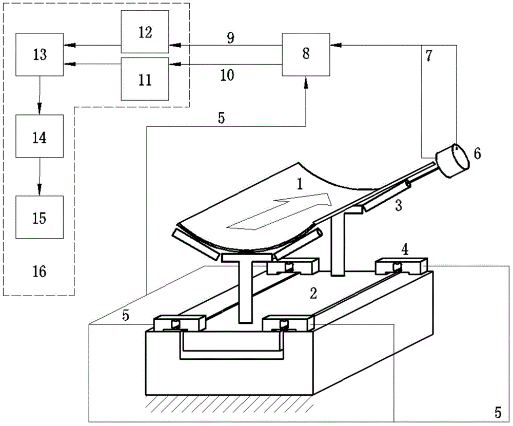
[0029] Such as figure 1 Shown is a specific embodiment of the all-optical sensor belt conveyor weighing device of the present invention. In this embodiment, this weighing device comprises belt conveyor belt 1, weighing frame 2, belt conveyor roller 3, and described belt conveyor roller 3 is arranged on weighing frame 2, and described belt conveyor belt 1 is located at belt conveyor roller 3 superior;

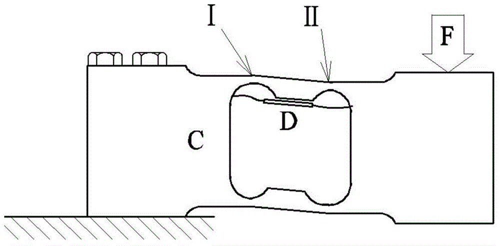
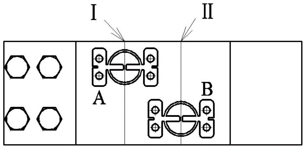
[0030] Four double-hole parallel beam load cells 4 equipped with or fixedly equipped with FBG strain gauges are arranged on the weighing frame 2;

[0031] The speed optical fiber code wheel sensor 6 is connected with the belt conveyor roller 3;

[0032] An optical fiber connection box 8, the double-hole parallel beam load cell 4 and the speed optical fiber code disc sensor 6 are respectively connected to the optical fiber connection box 8 thro...


PUM


Abstract

The invention discloses an all-fiber sensing belt conveyor weighing device and a weighing method thereof. The weighing device comprises a belt conveyor belt (1), a weighing frame (2), a belt conveyor rolling wheel (3), a fiber weighing sensor, a speed fiber sensor, a fiber splicing box (8) and a control room (16). The belt conveyor rolling wheel (3) is arranged on the weighing frame (2). The belt conveyor belt (1) is arranged on the belt conveyor rolling wheel (3). The fiber weighing sensor is arranged on the weighing frame (2). The speed fiber sensor is connected with the belt conveyor rolling wheel (3). The fiber weighing sensor and the speed fiber sensor are respectively connected with the fiber splicing box (8) via fibers. The fiber splicing box (8) and the control room (16) are connected via the fibers. The control room (16) processes the received signals and displays weighing weight and belt speed. The weighing device is suitable for more accurate weighing of bulk materials in dusty, moist and corrosive operation occasions and / or flammable and explosive operation occasions.

Description

technical field [0001] The invention relates to the technical field of flow meter weighing of bulk materials, in particular to a belt conveyor weighing device and a weighing method with full optical fiber sensing. Background technique [0002] The belt scale is a device for continuous and automatic weighing of materials during the process of conveying materials by belt conveyors. Its main feature is that the weighing process is continuous and automatic without operator intervention, so it is widely used in fields closely related to the national economy, such as grain, coal, petrochemical, mining, metallurgy, building materials, pharmaceuticals and other fields. [0003] The birth of the belt scale has a history of more than one hundred years. In 1908, American Herbert Merrick invented a weighing device for belt conveyors. This invention created a method for measuring the flow of solid materials, known as the Merrick type mechanical Belt scales. [0004] With the developme...

Claims


Application Information

Patent Timeline
Patent Type & Authority Patents(China)
IPC IPC(8): G01G11/00
Inventor 吴天平周卫东李维来李汉福张泽远李开福潘建军
Owner CHINA PETROLEUM & CHEM CORP
Why Eureka
Try Eureka