Supercharge Your Innovation With Domain-Expert AI Agents!

Flexible temperature difference generation micro-unit structure

A thermoelectric power generation, micro-unit technology, applied in electrical components, generators/motors, etc., can solve the problems of thermoelectric power generation unit failure, insufficient stability of thermoelectric generators, easy fracture of alloy materials, etc., and achieve the effect of avoiding failure.

Inactive Publication Date: 2014-06-25
ZHEJIANG UNIV
View PDF0 Cites 3 Cited by
  • Summary
  • Abstract
  • Description
  • Claims
  • Application Information

AI Technical Summary

Problems solved by technology

[0004] Existing miniature flexible thermoelectric power generation components usually arrange thermoelectric arms directly on the substrate or use flexible connections between bulk miniature thermoelectric materials, because the internal environment of the human body has many curved surfaces and the human body is flexible, and the thermoelectric arms are often squeezed. Stability of this type of thermoelectric generator is not enough, so it is necessary to have better flexibility of thermoelectric power generation components; the use of bismuth telluride and its alloys can improve the power generation of thermoelectric power generation devices, but bismuth telluride (BiTe ) The mechanical properties of the material are poor, and the material is brittle. When subjected to pressure or impact, the bismuth telluride and its alloy materials directly processed on the flexible substrate are easy to break, which makes the thermoelectric power generation unit invalid

Method used


Image

  • Flexible temperature difference generation micro-unit structure
  • Flexible temperature difference generation micro-unit structure
  • Flexible temperature difference generation micro-unit structure

Examples


Embodiment Construction

[0024] The present invention will be further described below in conjunction with the accompanying drawings and embodiments.

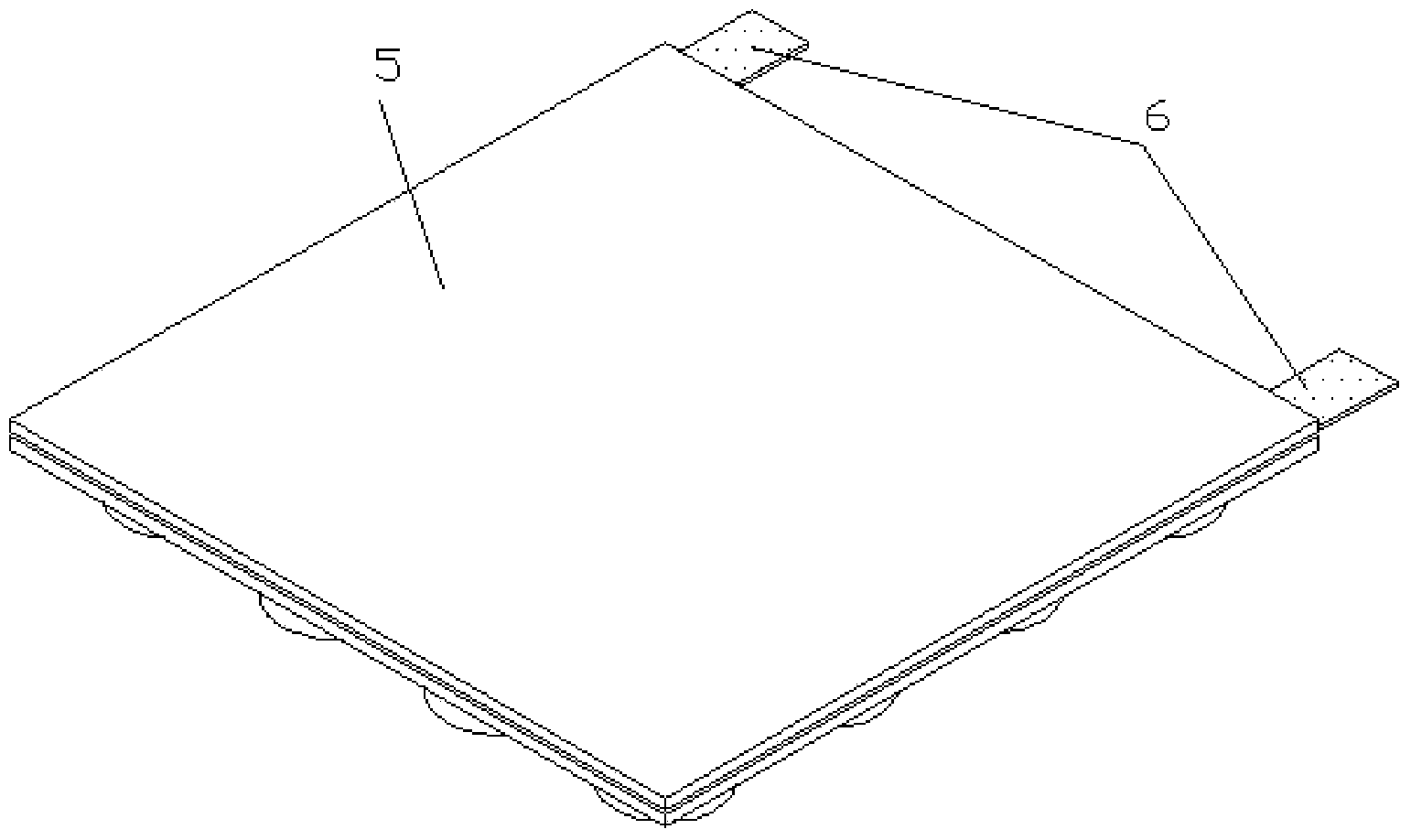
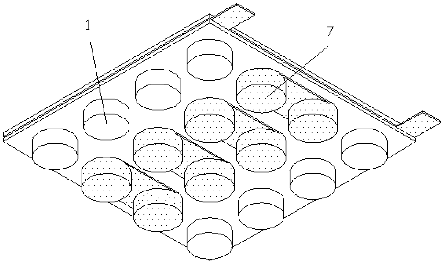
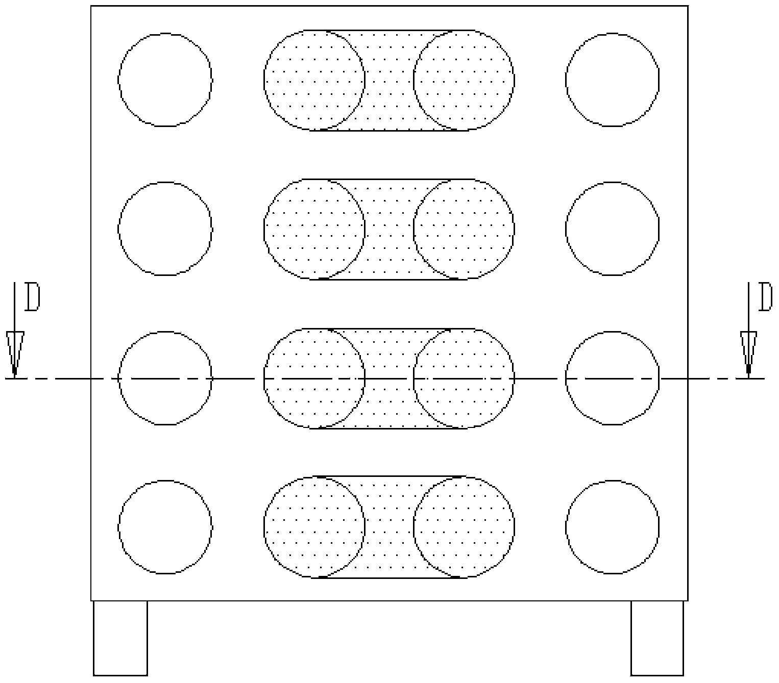
[0025] Such as Figure 9 As shown, the present invention casts polyimide in the lower film 9 of the polyimide base mold, extrudes with the upper mold 8 of the polyimide base mold, and solidifies into the base 1 of the honeycomb circular cavity. Such as figure 2 , image 3 , Figure 4 , Figure 5 , Figure 6 , Figure 7 , Figure 8 As shown, the present invention has multiple rows and multiple even columns of honeycomb circular cavities on the substrate 1 (there are four rows and four rows of circular cavities in the figure, as long as figure 2 The number of columns can be increased by arraying the two columns in the middle), except for the two rows of circular cavities on the edge, there is a microhole at the bottom of the other circular cavities, such as Figure 11 As shown, the silver-based nanoparticle ink 2 is drip-coated with silver-based...


PUM


Abstract

The invention discloses a flexible temperature difference generation micro-unit structure. Multiple rows of and multiple even-number lists of beehive-shaped circular cavities are arranged on a base. Micro holes are formed on the bottoms of the other circular cavities except the circular cavities in the two lists on the rim, the inner bottoms of the circular cavities provided with the micro holes are coated with silver base nano particle ink which fills the micro holes and covers the bottoms of the circular cavities. P type electric heating arms and N type electric heating arms fill in each row of the circular cavities at interval, and the top end of each pair of the P type heat electric arm and the N type heat electric arm is connected by an upper layer copper wire. The N type heat electric arms and the P type heat electric arms which are provided with micro holes are arranged in a group, and the outer bottom faces of the circular cavities provided with the micro holes are connected by a lower layer cooper wire to form a flexible temperature difference generation unit structure. The invention is highly flexible and stable, and, when the temperature difference generation unit receives impacts, the substrate which wraps the heat electric arms can prevent the bismuth telluride electric heating material which has poor ductility from cracking and losing efficacy. The flexible temperature difference generation micro-unit structure can provide energy to the medical micro device implanted into the body and has a popularization application value.

Description

technical field [0001] The invention relates to a thermoelectric power generation device, in particular to a flexible thermoelectric microunit structure. Background technique [0002] Implantable medical devices in the body are used more and more widely, such as pacemakers, defibrillators, drug pumps, etc., which can replace or improve the function of organs or treat certain diseases. Providing durable and stable energy supply for implantable medical devices is a research hotspot and difficult problem in the world today. At present, there are several power sources used in implantable medical devices: lithium batteries, biofuel cells, nuclear batteries, wireless energy transmission, etc. Micro lithium batteries often have a short lifespan, and patients need to replace batteries for a long time, causing a lot of pain; nuclear batteries can work for more than ten years, but they are generally large in size and have toxicity and radiation to the human body; biofuel cells use en...

Claims


Application Information

Patent Timeline
IPC IPC(8): H02N11/00
Inventor 梅德庆刘海燕姚喆赫陈子辰
Owner ZHEJIANG UNIV
Features
  • R&D
  • Intellectual Property
  • Life Sciences
  • Materials
  • Tech Scout
  • Unparalleled Data Quality
  • Higher Quality Content
  • 60% Fewer Hallucinations
Learn More