
Connection method of dissimilar metal rings and metal pipe fitting assembly joints

A technology of metal pipe fittings and dissimilar metals, which is applied in the field of solid connection of dissimilar metals, can solve the problems of not being able to obtain high-quality impact joints with wave interfaces and jets, not being able to obtain metallurgical joints, and difficult to meet high sealing and high strength, etc., to achieve Improved relative positional relationship, high strength, optimized impact speed and angle matching effects

Active Publication Date: 2016-08-24
HARBIN INST OF TECH
View PDF5 Cites 0 Cited by
  • Summary
  • Abstract
  • Description
  • Claims
  • Application Information

AI Technical Summary

Problems solved by technology

[0005] The purpose of the present invention is to provide a high-speed connection device and method for assembling joints between dissimilar metal rings and metal pipe fittings, so as to solve the problem that the existing magnetic pulse connection method cannot produce a suitable Therefore, the wave interface and jet phenomenon that must be possessed by high-quality impact joints cannot be obtained
Therefore, only plastic deformation connection joints can be obtained, but metallurgical connection joints cannot be obtained, and it is difficult to meet the requirements of high airtightness and high strength.

Method used


Image

  • Connection method of dissimilar metal rings and metal pipe fitting assembly joints
  • Connection method of dissimilar metal rings and metal pipe fitting assembly joints
  • Connection method of dissimilar metal rings and metal pipe fitting assembly joints

Examples


specific Embodiment approach 1

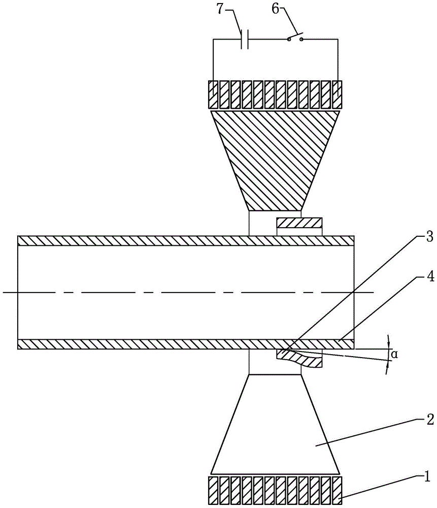
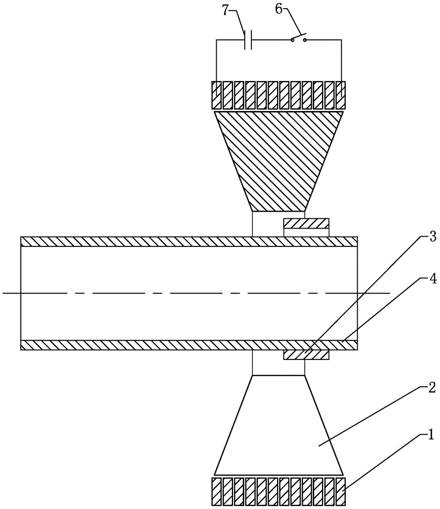
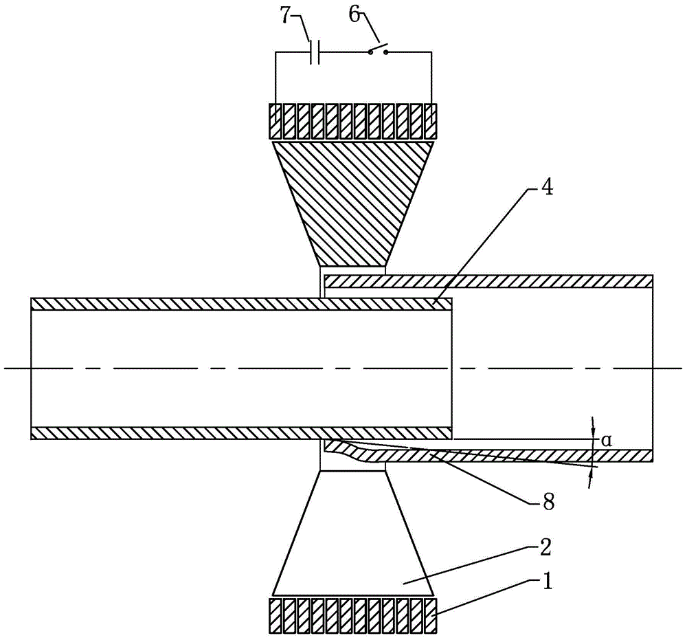
[0021] Specific implementation manner one: such as Figure 1a , Figure 1b , Figure 2a , Figure 2b As shown, the high-speed connection device of the dissimilar metal ring and the metal pipe assembly joint of this embodiment includes a solenoid coil 1, a magnetic collector 2, a discharge switch 6 and a capacitor bank 7. The central part of the magnetic collector 2 is provided with an axial through The inner cavity (the axial cross-sectional shape of the side wall of the magnetic collector 2 is an isosceles trapezoid), the length of the inner side of the magnetic collector 2 is less than the length of its outer side, and the side of the magnetic collector 2 is provided with an axially communicating with the inner cavity of the magnetic collector 2 In the longitudinal seam, the solenoid coil 1 is sleeved on the outside of the magnetic collector 2. The solenoid coil 1 and the magnetic collector 2 are arranged coaxially. One end of the capacitor bank 7 is connected to a terminal of ...

specific Embodiment approach 2

[0022] Specific implementation manner two: combination Figure 1a , Figure 1b It is explained that a method of this embodiment uses the high-speed connecting device to realize the connection method of the dissimilar metal ring and the metal pipe fitting assembly joint, and the method includes the following steps:

[0023] Step 1: Set the metal pipe 4 in the inner cavity of the magnetic collector 2 first, set the metal ring 3 on the metal pipe 4, and charge the capacitor bank 7 to a preset voltage according to the principle of the magnetic pulse forming process ;

[0024] Step 2: After the capacitor bank 7 is charged, the discharge switch 6 is closed, and the electric energy stored in the capacitor bank 7 is discharged to the solenoid coil 1 through the lead wire. The current passing through the solenoid coil 1 has the characteristics of instantaneous attenuation and oscillation, according to The law of electromagnetic induction and the skin effect produce induced current on the out...

specific Embodiment approach 3

[0026] Specific implementation mode three: combination Figure 1a , Figure 1b It is explained that in step one of this embodiment, the capacitor bank 7 is charged to 3-20kV; in step two, when the impact velocity at the contact point reaches 210-300m / s, between the inner surface of the metal ring 3 and the outer surface of the metal pipe 4 When the formed acute angle α is 10°, the axial movement speed of the contact point reaches 1100 to 1700 m / s. Severe shear deformation causes the thin layer of metal to peel off from the inner and outer surfaces of the metal pipe, and fly out from the front end of the impact contact point together with oxide and air, forming a jet phenomenon, so that the surface to be connected is exposed to clean metal under the impact pressure , Forming a metallurgical bonding interface. The technical features not disclosed in the embodiment are the same as those in the second embodiment.


PUM

PropertyMeasurementUnit
thicknessaaaaaaaaaa
lengthaaaaaaaaaa
lengthaaaaaaaaaa

Abstract

The invention discloses a high-speed connecting device and method for a dissimilar metal ring and a metal pipe fitting assembly joint, belongs to the field of solid connection of dissimilar metal and solves the problem that metallurgy connecting joints cannot be obtained by an existing magnetic pulse connection method for connecting a metal ring with a joint of a metal pipe fitting. The high-speed connecting device is characterized in that the lateral side of a magnetism collector is axially provided with a longitudinal seam communicated with an inner cavity of the magnetism collector, a screw pipe coil sleeves the magnetism collector, one end of a capacitor bank is connected with a terminal of the screw pipe coil, the other end of the capacitor bank is connected with one end of a discharging switch, and the other end of the discharging switch is connected with the other terminal of the screw pipe coil. The first high-speed connecting method includes charging the capacitor bank to a preset voltage value; forming an acute angle alpha between the inner side of the metal ring and the outer side of the metal pipe fitting, and finally obtaining an assembly joint of the dissimilar metal ring and the metal pipe fitting. The second high-speed connecting method includes replacing the metal ring by a metal pipe billet, and cutting a non-joint connecting portion of the metal pipe billet after connecting the metal pipe billet and the metal pipe fitting. The high-speed connecting device and method are used for connection of the dissimilar metal and the pipe fitting assembly joint.

Description

Technical field [0001] The invention relates to a device and method for connecting a dissimilar metal ring and a metal pipe fitting assembly joint, and belongs to the field of solid connection of dissimilar metals. Background technique [0002] Dissimilar metal rings are often used in the assembly of metal or non-metallic pipe-shaped parts with another metal pipe-shaped part, which plays a role of positioning, pressing and even sealing, such as the assembly of high-strength non-metallic hydraulic pipes and metal pipe-shaped joints through steel rings or The aluminum alloy ring is realized. The assembly of the titanium alloy tube and the titanium alloy butt joint of the high-pressure hydraulic pipeline on the aircraft engine is realized by the copper ring, and the steel body and the copper belt of the aircraft shell are assembled and connected. The copper belt plays the role of sealing and guiding the high-pressure propelling gas when the shell is launched, and plays a key role in...

Claims


Application Information

Patent Timeline
Patent Type & Authority Patents(China)
IPC IPC(8): B23P19/00
CPCB23K20/06B23K2101/06B23K2103/18
Inventor 于海平赵岩范志松李春峰
Owner HARBIN INST OF TECH
Learn More