Combined pulse detonation engine detonation chamber

A technology of pulse detonation and engine, which is applied in mechanical equipment, intermittent injection devices, etc., can solve the problems that the shock wave focusing concave cavity is not concave, and does not form high-frequency detonation.

Inactive Publication Date: 2014-07-02
NORTHWESTERN POLYTECHNICAL UNIV
View PDF4 Cites 15 Cited by
  • Summary
  • Abstract
  • Description
  • Claims
  • Application Information

AI Technical Summary

Problems solved by technology

[0004] Although the operating frequency of the two-stage pulse detonation engine is very high, theoretically it can reach tens of kilohertz, but the existing experimental research shows that the combustion mode in the concave cavity is mainly deflagration, and no high-frequency detonation is formed.
There are many reasons for this, such as the combustion of the pre-combustion chamber failed to produce a high-temperature small-molecule combustible gas mixture rich in active radicals, and the concave surface of the shock-wave focusing concave cavity is not the optimal form

Method used


Image

  • Combined pulse detonation engine detonation chamber
  • Combined pulse detonation engine detonation chamber
  • Combined pulse detonation engine detonation chamber

Examples


Embodiment 1

[0021] This embodiment is the first preferred solution, the two jet tubes can be ignited in time; that is, the two pre-detonation tubes are sequentially ignited, so that the operating frequency of the main detonation chamber is twice the operating frequency of the pre-detonation tube, thereby extremely Greatly improve the operating frequency of the engine.

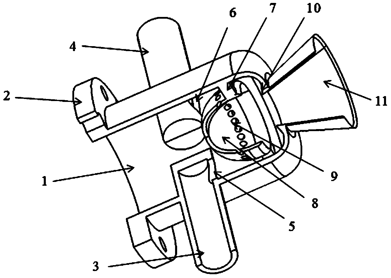
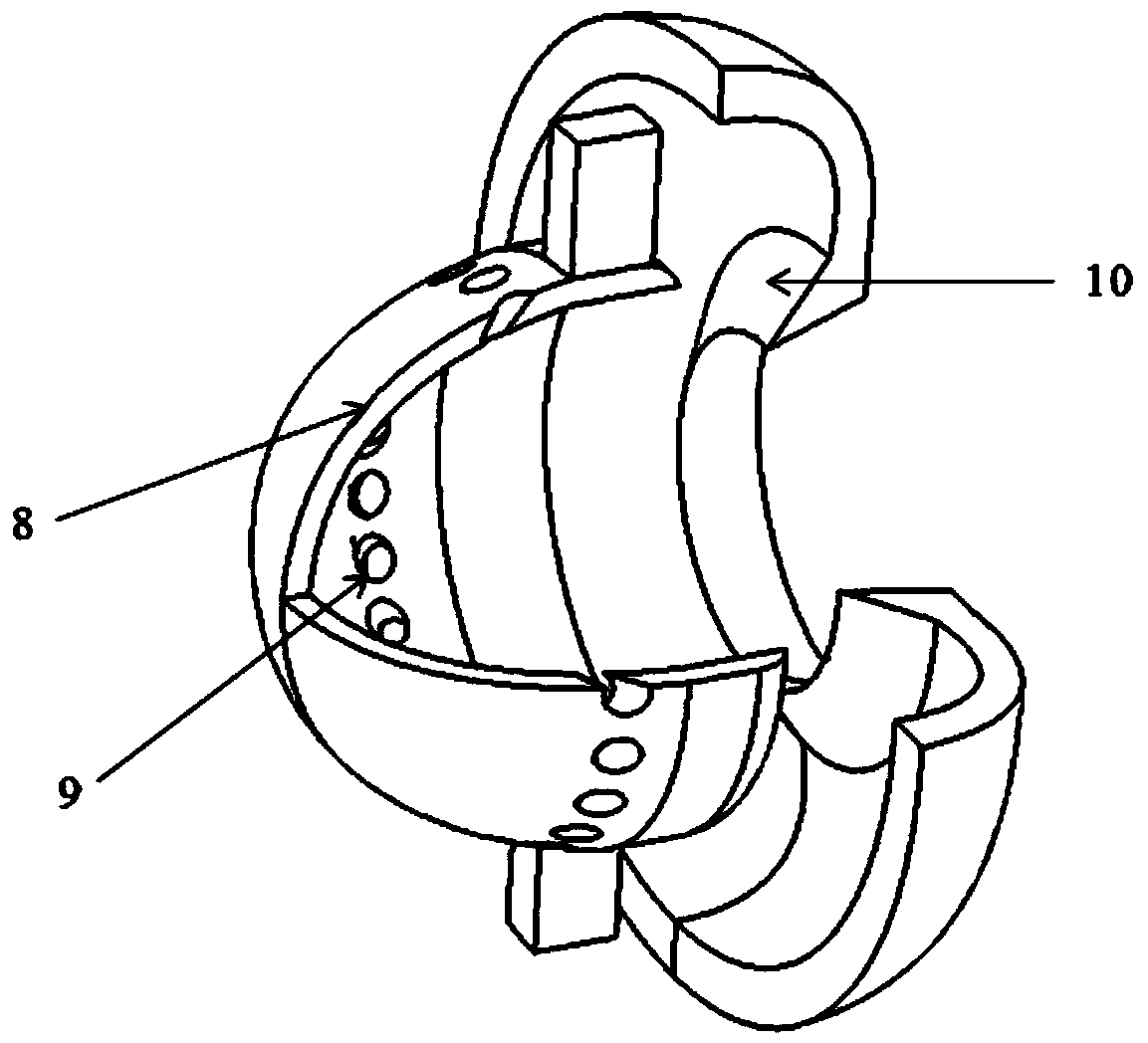
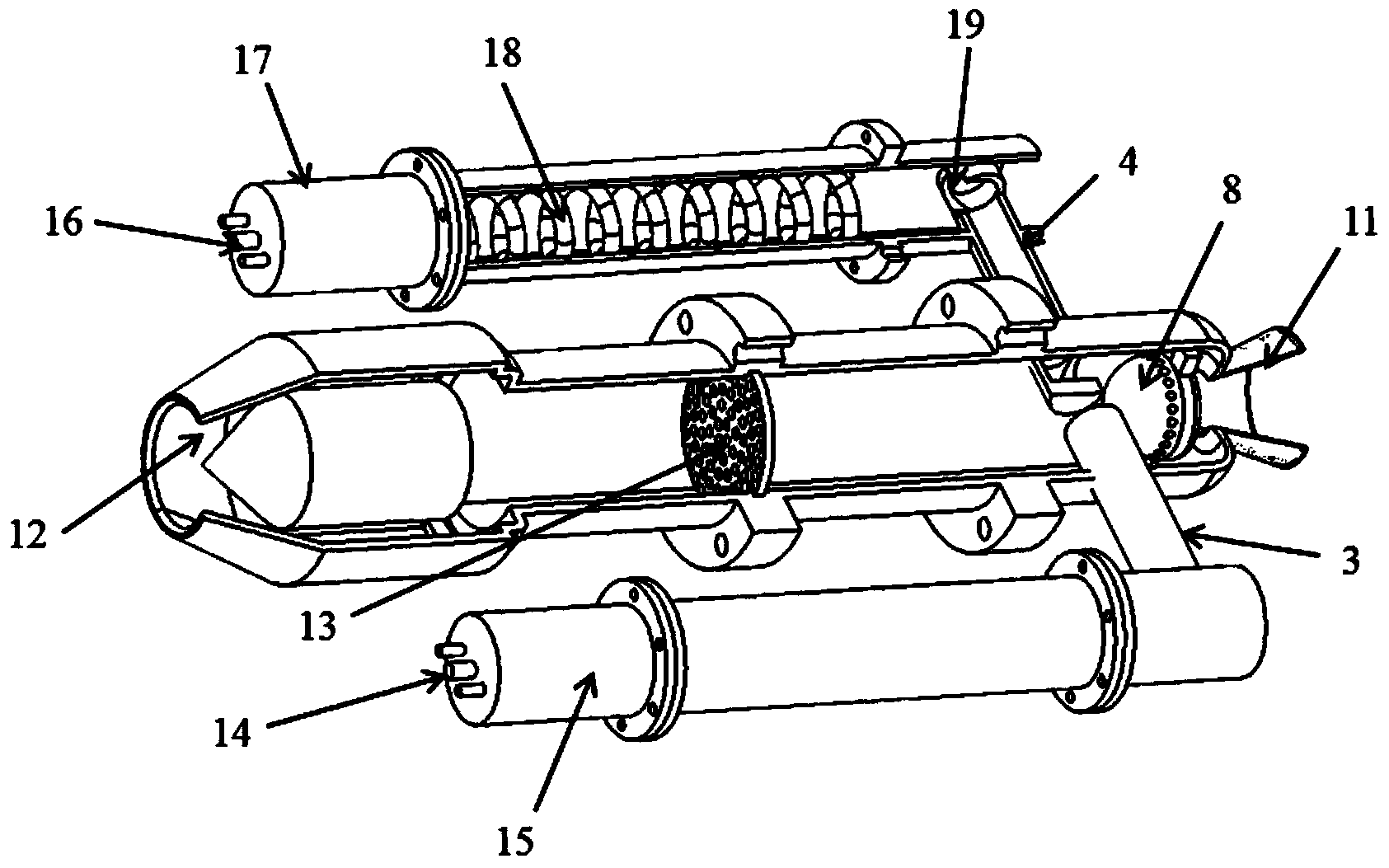
[0022] refer to figure 1 , figure 2 , image 3 , The detonation chamber of the combined pulse detonation engine of this embodiment consists of a main detonation chamber 1, a flange 2, a first jet pipe 3, a second jet pipe 4, a first jet pipe outlet 5, and a second jet pipe outlet 6 , strut 7, shock wave focusing cavity 8, oblique jet hole 9, deflector ring 10, tail nozzle 11, air inlet 12, orifice plate 13, first pre-explosion tube fuel inlet 14, first pre-explosion tube 15. The second pre-detonation tube fuel inlet 16, the second pre-detonation tube 17, the detonation enhancement device 18, the detonation jet drainage...

Embodiment 2

[0026] like Figure 4As shown, as the second preferred solution of the present invention, the number of jet tubes can be multiple, and a cross-symmetrical layout is formed with the engine 20 as the central axis under the permission of the space size. This cross-symmetrical layout can ensure the formation of detonation waves. In addition, more jet tubes can be divided into multiple groups, and each group of jet tubes is sequentially ignited to work. The operating frequency of the main detonation chamber of the engine is the operating frequency of the pre-explosion tube multiplied by the number of groups, thereby greatly increasing the operating frequency of the engine. In this embodiment, the four pre-explosion tubes are divided into two groups, and the two groups of pre-explosion tubes are fixed in a cross-symmetrical manner. The two opposite pre-explosion tubes form a group. And the filling of oxidant, so as to precisely control the ignition of the main detonation chamber 1....

Embodiment 3

[0028] As a third preferred solution of the present invention, the jet tube is arranged in a ring around the main detonation chamber 1, and this ring layout makes the pre-explosion tube a small booster engine, which is used as a booster device for supersonic flight of the engine.

[0029] When the detonation chamber of the combined pulse detonation engine of the present invention was working, the pre-explosion tube became a system independently, and the fuel and The oxidant is precisely controlled by the solenoid valve to realize accurate control of the ignition time of the main detonation chamber 1. The main detonation chamber 1 starts to fill the main detonation chamber 1 with the fully mixed and atomized fuel-air mixture within the unit working cycle. When the main detonation chamber 1 is filled, the detonation wave formed by the pre-detonation tube passes through the first jet tube 3 And the second jet tube 4 starts firing the main detonation chamber. A deflagration wave ...


PUM


Abstract

The invention discloses a combined pulse detonation engine detonation chamber. An ignition combination mode of a two-stage shock wave focusing device and pre-detonation pipes is adopted. A main detonation chamber is connected with an engine, and a first pre-detonation pipe and a second pre-detonation pip are fixed on two sides of the engine, and are mounted parallelly to the main detonation chamber through a first jet pipe and a second jet pipe respectively. Detonation jet led out from pre-detonation pipe outlets by the jet pipes firstly fills the main detonation chamber and a shock wave focusing cavity via an intensively-mixed and atomized gas-oil mixture, after filling, the detonation jet led out from the pre-detonation pipes enters the detonation chamber from outlets of the jet pipes to ignite the oil-gas mixture in the detonation chamber, and deflagration waves with leading shock waves are formed to be propagated forwards. The deflagration waves form strong shock waves under the action of a flow guide ring, and the strong shock waves ignite an explosible oil-gas mixture to form detonation waves and generate high positive thrust. Initiation of explosion of the pulse detonation engine detonation chamber within a short distance is realized, so that the engine is shortened, and working frequency of the pulse detonation engine is increased.

Description

technical field [0001] The invention belongs to the technical field of detonation engines, and in particular relates to a combined pulse detonation engine detonation chamber. Background technique [0002] Propulsion systems using detonation waves to generate thrust include oblique detonation engines, rotary detonation engines, pulse detonation engines, two-stage pulse detonation engines, and the like. A pulse detonation engine is a propulsion system that uses periodic detonation waves to generate thrust. A general pulse detonation engine produces a slow combustion wave through spark plug ignition. After the slow combustion wave accelerates through obstacles, it forms a local hot spot, that is, the high temperature and high pressure area of ​​the overdriven detonation wave, and then forms a stable detonation wave that propagates forward. But it takes a long distance for the flame to accelerate to form a localized hot spot, limiting the frequency at which the engine can opera...

Claims


Application Information

Patent Timeline
Patent Type & Authority Applications(China)
IPC IPC(8): F02K7/02
Inventor 郑龙席卢杰胡明李晓丰
Owner NORTHWESTERN POLYTECHNICAL UNIV
Why Eureka
Try Eureka