Mobile LNG (Liquefied Natural Gas) supply device utilizing residual heat and waste heat

A gas supply device, mobile technology, applied in the container discharge method, equipment loaded into the pressure vessel, gas/liquid distribution and storage, etc., can solve the problem that the long-term stable gas supply and gasification speed of the gasifier cannot be achieved Slow, lack of gas supply safety and other problems, to achieve the effect of compact structure, fast start-up speed, fast gasification speed

Active Publication Date: 2014-07-02
SOUTH CHINA UNIV OF TECH
View PDF10 Cites 5 Cited by
  • Summary
  • Abstract
  • Description
  • Claims
  • Application Information

AI Technical Summary

Problems solved by technology

The technical solutions disclosed in the invention patent CN102606880A and the utility model patents CN201057357Y and CN201310744Y can alleviate this problem to a certain extent, but the above-mentioned technical solutions are lacking in the safety of gas supply, and the gasifier used in them has gasification Due to the disadvantages of slow speed, large floor area and poor environmental adaptability, it is impossible to achieve long-term stable gas supply, and it cannot be used in the case of large-scale maintenance of the pipeline network or long-term insufficient gas supply of the pipeline network.

Method used


Image

  • Mobile LNG (Liquefied Natural Gas) supply device utilizing residual heat and waste heat
  • Mobile LNG (Liquefied Natural Gas) supply device utilizing residual heat and waste heat

Examples


Embodiment

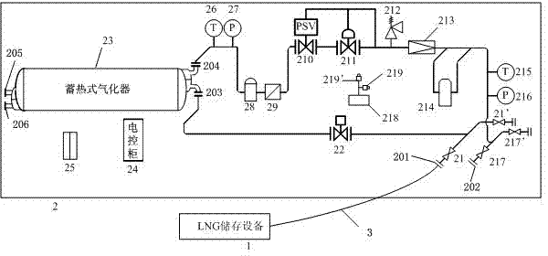
[0024] Such as figure 1 Shown is a schematic structural diagram of a mobile LNG gas supply device utilizing waste heat provided by the present invention, shown in the figure: LNG storage equipment 1, vehicle-mounted gasification pressure regulating container 2, LNG inlet flange 201, natural gas outlet flange 202, Liquid phase inlet flange 203, gas phase outlet flange 204, heating fluid inlet flange 205, heating fluid outlet flange 206, stop valves (21, 21', 217, 217'), emergency shut-off solenoid valve 22, accumulator Thermal vaporizer 23, electric control cabinet 24, portable dry powder fire extinguisher 25, first temperature sensor 26, first pressure sensor 27, over-liquid prevention device 28, filter 29, overpressure cut-off valve 210, pressure regulator 211 , safety release valve 212, flow meter 213, THT odorizer 214, second temperature sensor 215, second pressure sensor 216, combustible gas alarm 218, alarm probe 219, alarm probe 219', pipeline 3.

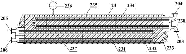
[0025] figure 2 It ...


PUM


Abstract

The invention discloses a mobile LNG (Liquefied Natural Gas) supply device utilizing residual heat and waste heat. The mobile LNG supply device comprises an LNG storage device and a vehicle-mounted vaporization pressure adjusting container, wherein a regenerative vaporizer is arranged in the vehicle-mounted vaporization pressure adjusting container; a first heat exchange pipe and a second heat exchange pipe are arranged inside the regenerative vaporizer; the inlets and outlets of the first heat exchange pipe and the second heat exchange pipe are formed in one pipe plate; end sockets at the two ends of the first heat exchange pipe and the second heat exchange pipe are partitioned into two chambers; the LNG storage device is connected with the regenerative vaporizer through a pipe. According to the mobile LNG supply device, externally connected power source or other power sources are not needed when gas is supplied; the LNG is vaporized through the residual heat and waste heat recycled by the regenerative vaporizer, the environment impact on a vaporization amount is extremely small, the gas supply amount of the device is large and the vaporization speed is fast; meanwhile, an electric control cabinet and a safety device are arranged so as to ensure the safety and reliability of gas supply; the mobile LNG supply device has the characteristic of being compact in structure, convenient to move, energy-saving and environment-friendly, fast in starting speed, strong in gas supply capability and environmental adaptability and high in safety performance and reliability.

Description

technical field [0001] The invention relates to the field of liquefied natural gas gas supply, in particular to a mobile LNG gas supply device utilizing waste heat. Background technique [0002] In the context of energy conservation and emission reduction, natural gas will soon become the dominant source of urban gas in my country. With the popularization of natural gas supply in cities, how to ensure the continuous and stable gas consumption of users during the maintenance and renovation process and the peak of gas consumption has become an important issue faced by gas companies. The technical solutions disclosed in the invention patent CN102606880A and the utility model patents CN201057357Y and CN201310744Y can alleviate this problem to a certain extent, but the above-mentioned technical solutions are lacking in the safety of gas supply, and the gasifier used in them has gasification Due to the disadvantages of slow speed, large floor area and poor environmental adaptabil...

Claims


Application Information

Patent Timeline
Patent Type & Authority Applications(China)
IPC IPC(8): F17C5/02F17C13/02F17C13/00F17C13/04
Inventor 樊栓狮孙超郎雪梅王燕鸿温永刚
Owner SOUTH CHINA UNIV OF TECH
Why Eureka
Try Eureka