Supporting insulator type high voltage induction sensor

A high-voltage sensor, supporting insulator technology, used in instruments, measuring current/voltage, measuring devices, etc., can solve the problems of false indication, inconvenient installation, increase production cost, etc. Misoperation, the effect of improving production efficiency

Inactive Publication Date: 2014-07-02
福建启和科技有限公司
View PDF10 Cites 4 Cited by
  • Summary
  • Abstract
  • Description
  • Claims
  • Application Information

AI Technical Summary

Problems solved by technology

When the positions of the two copper foils are slightly deviated and cannot be kept parallel, the capacitance formed by the two copper foils cannot accurately sense whether the high-voltage electrified body in the high-voltage equipment is charged, which often leads to false indications
At the same time, since the processing of copper foil requires special cutting and other operations, standardized industrial production cannot be carried out at present, which greatly affects the industrialization and promotion of sensors.
The use of existing inductive sensors also has the following disadvantages: 1. Since the sensor is in the process of inducing voltage signals, the distance between the sensor and the high-voltage electrified body (such as the high-voltage busbar) must be accurate and fixed, and the sensing surface of the sensor is also required to be in contact with the high-voltage electrified body. The surface of the body is s

Method used


Image

  • Supporting insulator type high voltage induction sensor
  • Supporting insulator type high voltage induction sensor

Examples


Example Embodiment

[0019] The present invention will be further described in detail below in conjunction with specific embodiments:

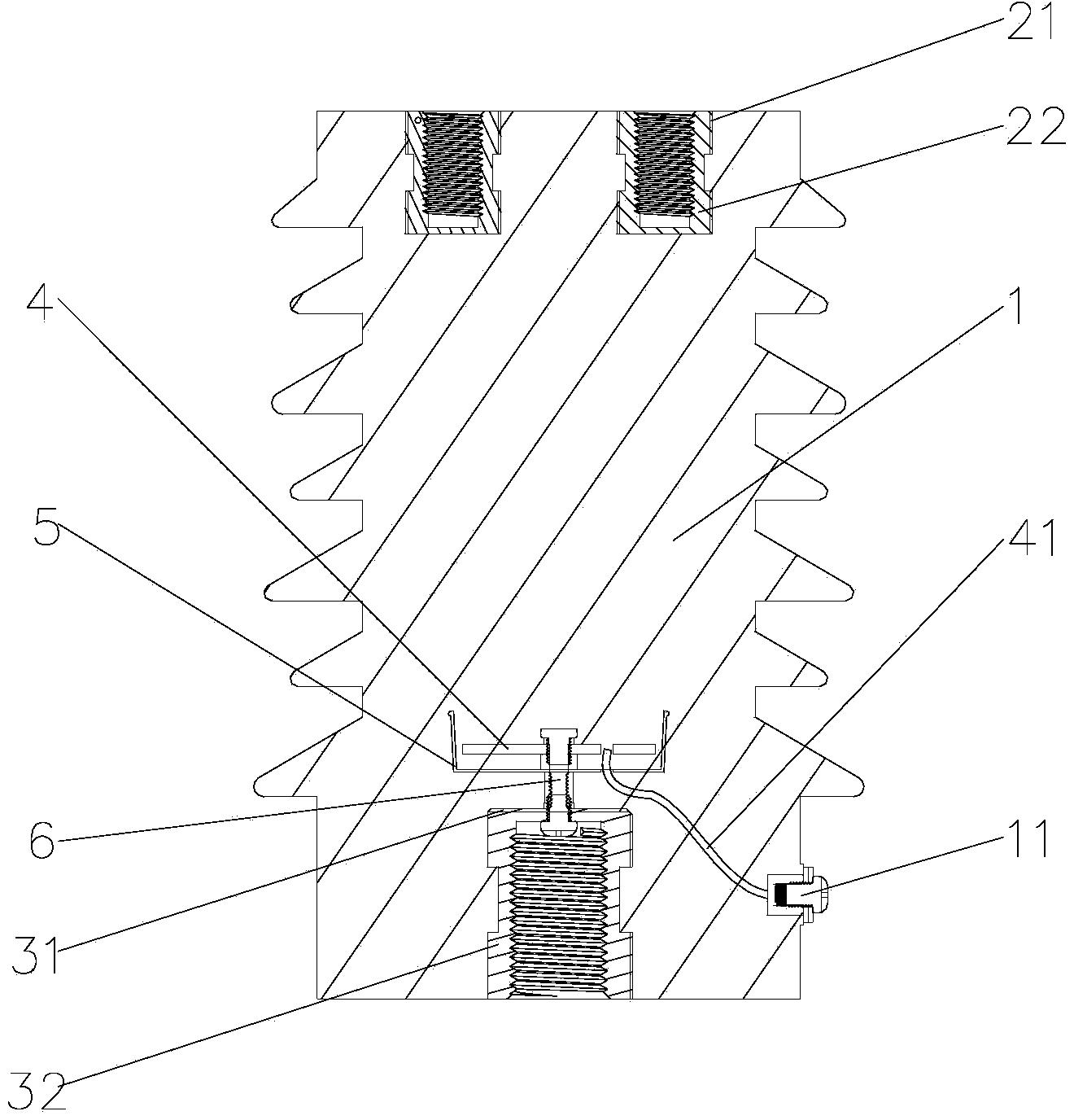
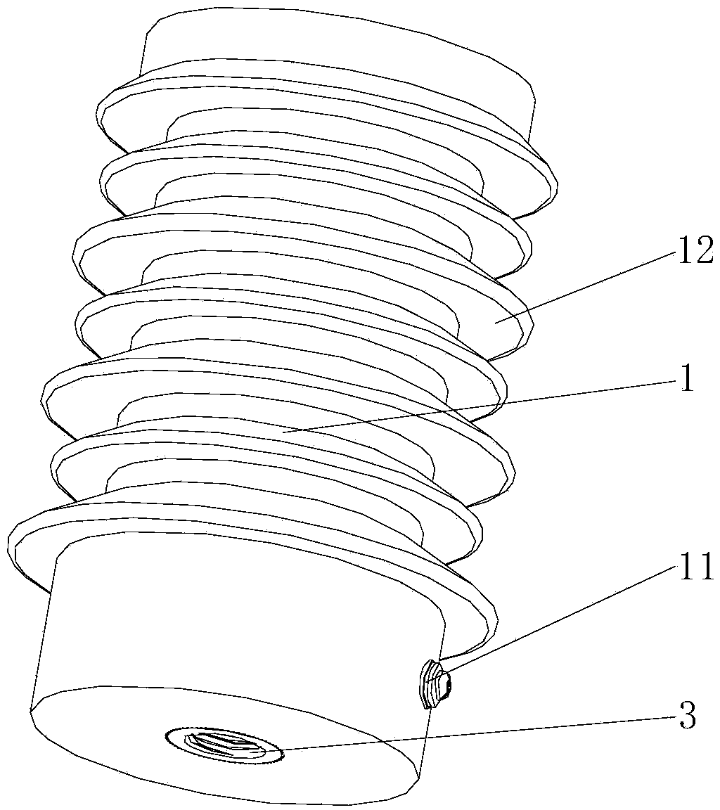
[0020] Such as figure 1 or figure 2 As shown, the present invention is a supporting insulator-type inductive high-voltage sensor, which is fixed in a high-voltage electrical equipment, and is set in an insulator 1. The upper end of the insulator 1 is provided with an upper flange for fixing high-voltage live bodies in the high-voltage electrical equipment 2. The lower end of the insulator 1 is provided with a lower flange 3 connected to high-voltage electrical equipment. A printed circuit board 4 for inducing electric field signals is provided between the upper flange 2 and the lower flange 3 in the insulator 1. The printed circuit board 4 is connected to the lower The opposite side of the flange 3 is provided with a shielding cover 5. The printed circuit board 4 and the shielding cover 5 are fixed with the lower flange 3 through the connecting piece 6; the other si...


PUM


Abstract

The invention discloses a supporting insulator type high voltage induction sensor. The supporting insulator type high voltage induction sensor is fixed in high-voltage electrical equipment, and comprises an insulator, an upper flange is arranged at the upper end of the insulator, a lower flange is arranged at the lower end of the insulator, a printed circuit board is arranged in the insulator, a shielding cover is arranged on the face, opposite to the lower flange, of the printed circuit board, and the printed circuit board and the shielding cover are fixed with the lower flange through a connecting piece. The other face of the printed circuit board is opposite to a high-voltage electrified body, and a signal line for outputting voltage signals is further arranged on the other face of the printed circuit board. Due to the fact that the printed circuit board is adopted to replace two pieces of existing copper foil to induct electric field signals, industrial production of the sensor can be achieved, and the production efficiency of the sensor is greatly improved. Meanwhile, due to the fact that the high-voltage electrified body can be fixed to the upper flange in the insulator, the high-voltage electrified body can be fixed conveniently, the distance between the high-voltage electrified body and the printed circuit board is fixed, the electric field signals in the high-voltage electrified body can be detected accurately and reliably, and wrong instructions and misoperations can be avoided.

Description

Technical field [0001] The present invention relates to a high-voltage sensor in high-voltage electrical equipment, in particular to a supporting insulator-type induction high-voltage sensor in high-voltage electrical equipment. Background technique [0002] High-voltage live work is dangerous, so a display device that can indicate whether high-voltage equipment is live is needed. Commonly used high-voltage live display devices usually include a sensor and a controller. At present, the sensors of domestic high-voltage live display devices are usually divided into two types: contact type and non-contact type. The contact sensor uses the capacitor to divide the high voltage to extract the signal, thereby judging whether the measured object is charged. This kind of sensor is prone to capacitor breakdown and cause accidents. [0003] The current non-contact sensors (ie inductive sensors) use the principle of inducing high-voltage electric field signals. The sensor is installed under o...

Claims


Application Information

Patent Timeline
IPC IPC(8): G01R19/155G01R1/04
Inventor 朱方铁王家余洪建盛
Owner 福建启和科技有限公司
Why Eureka
Try Eureka