Multi-core optical fiber, sensing device with same and operating method of sensing device

A technology of multi-core optical fiber and sensing device, which is applied in the direction of multi-core optical fiber, the use of optical devices to transmit sensing components, multi-layer core/clad optical fibers, etc. Solve problems such as single test parameters to achieve the effect of eliminating fluctuations in optical power, good market prospects, and good application prospects

Inactive Publication Date: 2014-07-02
XIAN JINHE OPTICAL TECH
View PDF7 Cites 32 Cited by
  • Summary
  • Abstract
  • Description
  • Claims
  • Application Information

AI Technical Summary

Problems solved by technology

[0002] Chinese Patent Application No. 201120130642.5 "Temperature Sensing Device Based on Dual-Core Optical Fiber" discloses a temperature sensing device that uses a broadband light source, a dual-core optical fiber and a spectrum analyzer. When the temperature changes, two The distance between the two cores will also change, resulting in the change of the wavelength of the optical signal that is coupled to the core that injects the broadband optical signal into the core that is not injected with the optical signal, and the change is detected by the optical spectrum analyzer, thereby completing the temperature measurement. It has a simple structure and a wide temperature monitoring range, but its test parameters are single, the instruments are expensive, and distributed monitoring cannot be realized
[0003] Existing distributed or quasi-distributed optical fiber sensing devices are inspection devices based on backscattered light in optical fibers, including the most commonly used optical time domain reflectometer (OTDR), optical fiber Raman temperature sensing devices, Brillouin scattering sensing device and fiber Bragg grating sensing device, in the first three sensing devices, since the backscattered light containing sensing information in the optical fiber is very small compared to the incident light, the ratio of backscattered light to The power of the forward transmission optical signal is three to six orders of magnitude smaller, so the detection of backscattered light is more difficult. In order to remove the noise, it often needs to be processed many times by the sampling integrator to extract the weak signal, which makes the monitoring equipment more complicated and more expensive. High, real-time performance is poor, and the maximum monitoring distance is less than 100 kilometers; while the quasi-distributed optical fiber sensing device composed of fiber Bragg gratings has a strong reflected optical signal, but the optical signal between the optical fiber gratings is easy to detect. Mutual interference, so the number of fiber gratings is small, and the number of fiber gratings on each fiber is only a few dozen at most, making it difficult to realize long-distance distributed monitoring
[0004] On the other hand, the existing optical fiber communication technology is developing rapidly, and its unrelayed communication distance can easily exceed hundreds of kilometers. If erbium-doped or Raman optical fiber amplifiers are used, it can reach thousands of kilometers. The main reason is that the previous The intensity of the optical signal propagating in the forward direction is far greater than that of the backscattered optical signal. If there is a distributed sensing device based on monitoring the change of the optical signal during forward transmission, the distance of distributed optical fiber monitoring can be greatly extended. However, No such device has been found so far

Method used


Image

  • Multi-core optical fiber, sensing device with same and operating method of sensing device
  • Multi-core optical fiber, sensing device with same and operating method of sensing device
  • Multi-core optical fiber, sensing device with same and operating method of sensing device

Examples


Embodiment 1

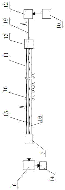
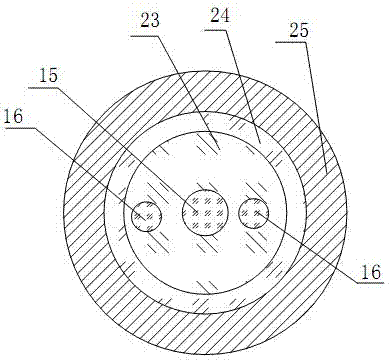
[0053] like figure 1 , figure 2 , image 3 and Figure 4 Shown is a multi-core optical fiber and an optical fiber sensing device based on the multi-core optical fiber. The optical fiber sensing device includes a control module 10, a light source module 12, a coupling module-13, a photodetector module-7 and a processing module 6, and the control module 10 is connected to the light source module 12 and controls the latter to send an optical signal, preferably a pulsed light signal, the light source module 12 is connected to the coupling module one 13 through an auxiliary optical fiber 19, and the coupling module one 13 is connected to one end of the multi-core optical fiber 11 connection, the multi-core optical fiber 11 has at least three cores arranged in the inner cladding 23, one of which is the transmission core 15, and the other cores are the sensing core 16, at least one sensing core 16 The length is different from the length of the transmission core 15; the coupling m...

Embodiment 2

[0072] like Figure 6 A kind of optical fiber sensing device shown, differs from embodiment 1 in that the other end of the multi-core optical fiber 11 is connected to the coupling module 3 4, the coupling module 3 4 includes three channels, and each channel is connected to each other. There is no interference, at least two sensing cores 16 and transmission cores 15 in the multi-core optical fiber 11 are respectively connected to three channels, and are respectively connected with the optical detector module 17 and the optical detection module 1 through the coupling module 3 4 The sensor module two 8 is connected to the photodetector module three 5; the photodetector module one 7, the photodetector module two 8 and the photodetector module three 5 are connected to the processing module 6.

[0073] The operation steps of the program are as follows:

[0074] 1) Including the sensing fiber 11, the transmission fiber core 15 and the sensing fiber core 16 contained in it have diffe...

Embodiment 3

[0080] like Figure 7 As shown, the difference between this embodiment and Embodiment 1 is: an optical fiber sensing device based on a multi-core optical fiber 11, including a control module 10, a light source module 12, a coupling module-13, an optical detector module-7 and a processing module 6. The control module 10 is connected to the light source module 12 and controls the latter to send out optical signals. The light source module 12 is connected to the coupling module one 13, and the coupling module one 13 is connected to one end of the multi-core optical fiber 11. The multi-core optical fiber 11 is that at least three fiber cores are arranged in the inner cladding 23, wherein one fiber core is the transmission fiber core 15, and the other fiber cores are the sensing fiber core 16, and the length of at least one sensing fiber core 16 is the same as that of the transmission fiber core 15. The lengths are different; the coupling module one 13 has at least two channels, ea...


PUM


Abstract

A multi-core optical fibre and a sensor based on the multi-core optical fibre and a running method therefor. The multi-core optical fibre comprises a transmission fibre core (15) and a plurality of sensing fibre cores (16), the length of the sensing fibre core (16) being not less than the length of the transmission fibre core (15). The sensor based on the multi-core optical fibre comprises a light source module (12), the multi-core optical fibre and optical detector modules (5, 7, 8). The light source module (12) injects optical signals in the transmission fibre core (15). The optical detector modules (5, 7, 8) detect the variation of optical signals in all or a part of the sensing fibre cores (16), eliminate interference through the comparison of the response of more than two sensing fibre cores (16) to the physical quantities to be detected in one and the same position, and improve the test accuracy. Also disclosed is a corresponding running method for the sensor based on the multi-core optical fibre.

Description

technical field [0001] The present invention relates to a novel multi-core optical fiber and a sensing device based on the multi-core optical fiber, in particular to a multi-core optical fiber containing three cores or more than three cores, and a point sensor based on the multi-core optical fiber. Or distributed optical fiber sensing device and method of operation thereof. Background technique [0002] Chinese Patent Application No. 201120130642.5 "Temperature Sensing Device Based on Dual-Core Optical Fiber" discloses a temperature sensing device that uses a broadband light source, a dual-core optical fiber and a spectrum analyzer. When the temperature changes, two The distance between the two cores will also change, resulting in the change of the wavelength of the optical signal that is coupled to the core that injects the broadband optical signal into the core that is not injected with the optical signal, and the change is detected by the optical spectrum analyzer, thereb...

Claims


Application Information

Patent Timeline
Patent Type & Authority Applications(China)
IPC IPC(8): G02B6/036G01D5/353
CPCG02B6/036G01D5/00G01D5/35374G02B6/02042
Inventor 杜兵
Owner XIAN JINHE OPTICAL TECH
Why Eureka
Try Eureka