

Double-wire arc welding power system based on sinusoidal wave modulating pulses
A technology of sine wave modulation and power supply system, which is applied to arc welding equipment, manufacturing tools, welding equipment, etc., and can solve problems such as lack of system theory regularity
- Summary
- Abstract
- Description
- Claims
- Application Information
AI Technical Summary
Problems solved by technology
Method used
Image

Examples
Embodiment Construction
[0075] The present invention will be further described below in conjunction with specific examples.
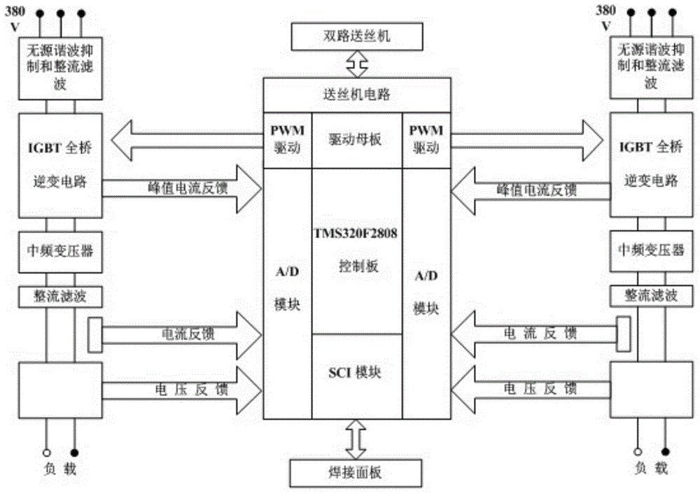
[0076] The twin-wire arc welding power supply system based on sine wave modulation pulse described in this embodiment includes:
[0077] Mathematical model for sine wave modulation pulse, used to convert the welding pulse current I i The peak value and base value of the value change according to the law of sine waves, forming the peak value and base value current sequence value;
[0078] The control detection circuit with DSP as the control core is used to realize the closed-loop control of the twin-wire arc welding power supply system to ensure that the output current and voltage of the system have a stable closed-loop controllability. The DSP is used for flexible programming to realize the digitalization of the control process of the system. At the same time, on the basis of the above mathematical model, the sine wave modulation pulse technology is realized, so that the wel...
PUM
 Abstract
Description
Claims
Application Information