Seal valve material returning system for chemical loop combustion system

A technology of chemical chain combustion and sealing valve, which is applied in the direction of burning fuel in the melting state, fluidized bed combustion equipment, combustion method, etc., can solve the problems of artificial control of material flow, poor material flow and unstable operation , to achieve the effect of simple structure, convenient manufacturing and installation, improving stability and reliability

Active Publication Date: 2014-07-09
STATE GRID CORP OF CHINA +2
View PDF8 Cites 4 Cited by
  • Summary
  • Abstract
  • Description
  • Claims
  • Application Information

AI Technical Summary

Problems solved by technology

They cannot realize the artificial control of the flow rate of the material. The air chambers at the lower part of the air distribution plate are very large, which provide air volume for both the loosening air chamber and the fluidization air chamber. The air distribution plates corresponding to the moving bed and the fluidized bed are all opened hole, the air volume is the same as or not much different from the air distribution method
Practice has shown that this kind of return device will have problems such as stagnation, fluidization dead angle, and poor material circulation during operation, resulting in unstable operation.

Method used


Image

  • Seal valve material returning system for chemical loop combustion system
  • Seal valve material returning system for chemical loop combustion system

Examples


Embodiment Construction

[0022] The present invention will be further described below in conjunction with the accompanying drawings.

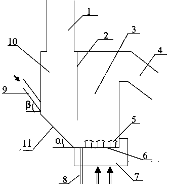
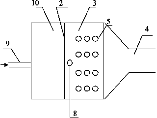
[0023] Depend on figure 1 , figure 2 As shown, the present invention mainly consists of a moving bed 10, a fluidized bed 3, a return pipe 4, a horizontal air distribution plate 6, an inclined air distribution plate 11, an air chamber 7 and an air cap 5. The effective area of ​​the moving bed 10 is smaller than the effective area of ​​the fluidized bed 3 (the effective area here refers to the projected area of ​​the moving bed and the fluidized bed on the horizontal plane). The horizontal air distribution plate 6 bears the weight of the whole device. The moving bed 10 and the fluidized bed 3 are separated by heat-resistant steel partitions 2. The partitions 2 are welded on both side walls, and the upper end is welded into the refractory layer on the top surface. Partition 2 is sealed with the welds on both side walls and the top surface, and a certain distance is le...


PUM


Abstract

The invention discloses a seal valve material returning system for a chemical loop combustion system. The middle lower part of the inner surface of the rear wall, which is opposite to a partition plate, of a moving bed is inclined towards the partition plate at an inclination angle of 30-60 degrees; a plurality of air outlet holes are formed in an air distribution plate of a fluidized bed on the left side of the partition plate; umbrella-shaped air caps are mounted on the air outlet holes; a moving bed on the right side of the partition plate is provided with an inclined air distribution plate; an adjustment air pipe is arranged at a position, which is close to an inclined plate, on the rear wall, which is opposite to the partition plate, of the moving plate and can supply intermittent swinging type lateral blowing air; the effective area of the moving bed of the whole device is smaller than that of the fluidized bed. The material returning device can avoid the phenomenon that material running is stopped, thereby avoiding the condition that gas in an air reactor backwards enters a fuel reactor; the controllability of the material throughput is improved, and the stability and reliability of running are improved; furthermore, the seal valve material returning system is simple in structure and convenient to manufacture. The seal valve material returning system is suitable for a loopseal system in the conventional chemical loop combustion reaction device, and lays a foundation for the research on a chemical loop combustion technology.

Description

technical field [0001] The invention relates to a sealing valve return material system in a chemical chain combustion system. Background technique [0002] The problem of global warming caused by greenhouse gas emissions is attracting people's attention. CO 2 As the most important greenhouse gas, the study of CO 2 Emission reduction technologies are imminent. CO in flue gas 2 Often diluted with large amounts of nitrogen, CO 2 The cost of separation and recovery is very high. High concentrations of CO are produced during combustion 2 or facilitate CO 2 It is an effective way to separate the gas phase mixture while eliminating the generation and emission of other pollutants. Chemical-Looping Combustion (CLC for short) is a new type of combustion with the above-mentioned characteristics, and has received more attention. The chemical looping combustion technology was first proposed by Ritcher et al. in 1983. The basic principle is to decompose the traditional fuel-air d...

Claims


Application Information

Patent Timeline
Patent Type & Authority Applications(China)
IPC IPC(8): F23C10/26F23C10/20
CPCY02E20/34
Inventor 闫晓沛张姣米翠丽李琼
Owner STATE GRID CORP OF CHINA
Why Eureka
Try Eureka