Photoelectric catalytic unit and photoelectric catalytic method

A technology of photoelectric catalysis and photocatalytic thin film, which is applied in the chemical/physical/physical chemical process of applying energy, etc., to achieve the effects of strong controllability, improved utilization of light energy, and improved photocatalytic efficiency

Inactive Publication Date: 2014-07-16
SHANGHAI INST OF CERAMIC CHEM & TECH CHINESE ACAD OF SCI
View PDF6 Cites 17 Cited by
  • Summary
  • Abstract
  • Description
  • Claims
  • Application Information

AI Technical Summary

Problems solved by technology

[0004] The present invention aims to overcome the defects of existing photocatalytic methods, and the present invention provides a photocatalytic device and photocatalytic method

Method used


Image

  • Photoelectric catalytic unit and photoelectric catalytic method
  • Photoelectric catalytic unit and photoelectric catalytic method
  • Photoelectric catalytic unit and photoelectric catalytic method

Examples


Embodiment 1

[0051] Coat 1mL of 0.5g / L graphene oxide dispersed in water on the surface of the thermoelectric device and dry it in a constant temperature drying oven at 60°C; refer to the literature (J.Phys.Chem.C2012,116,19413–19418.) to prepare FTO / Bi 2 WO 6 nano film;

[0052] Connect one end of the thermoelectric device to the FTO / Bi through conductive glue 2 WO 6 Fabrication of photocatalytic devices on nanofilms.

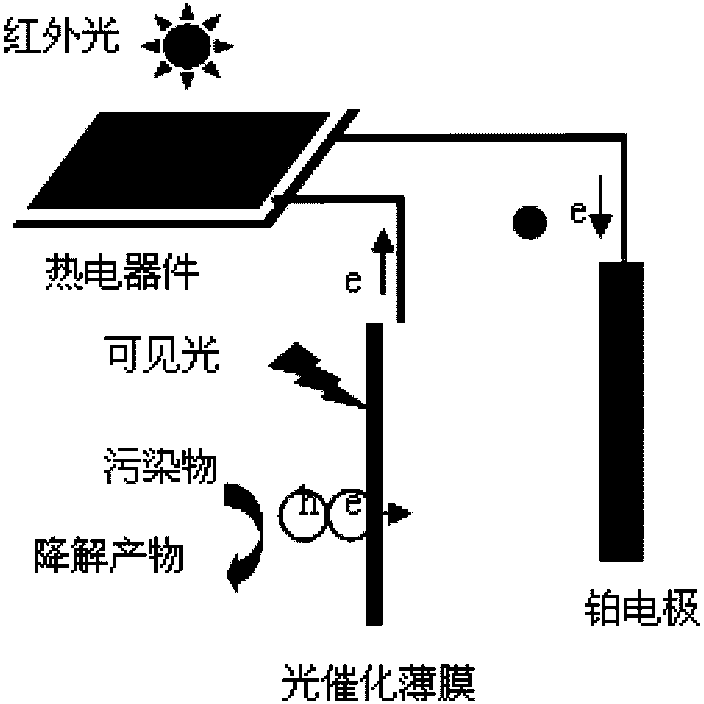
[0053] figure 1 It is a schematic diagram of a photoelectric catalysis device using thermoelectric devices and photocatalytic materials in this embodiment.

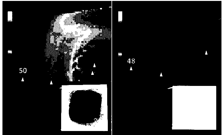
[0054] figure 2 It is the thermal imaging picture of the thermoelectric device in the present embodiment under the irradiation of infrared light, figure 2 In a is a thermoelectric device coated with a layer of graphene oxide, figure 2 where b represents an uncoated thermoelectric device. Depend on figure 2 It can be seen that after coating a layer of graphene oxide, the temperature difference between th...

Embodiment 2

[0059] The only difference between this embodiment and embodiment 1 is that the photocatalytic film adopted is commercialized TiO 2 (P25) deposited on the FTO film;

[0060] The rest of the content is exactly the same as described in Example 1.

[0061] After detection and analysis, it is known that: in this embodiment, the thermoelectric device and TiO 2 The photocatalytic degradation efficiency of phenol in water after photocatalytic film combined is higher than that of pure TiO 2 The photocatalytic degradation efficiency has been significantly improved.

Embodiment 3

[0063] The only difference between this embodiment and Embodiment 1 is that the surface coating of the thermoelectric device adopts CuS instead of graphene oxide;

[0064] The rest of the content is exactly the same as described in Example 1.

[0065] After detection and analysis, it is known that the temperature difference between the two ends of the thermoelectric device coated with CuS in this embodiment is significantly higher than that of the same condition without coating, and the temperature difference between the thermoelectric device and Bi 2 WO 6 The photocatalytic degradation efficiency of phenol in water after the combination of photocatalytic film is higher than that of pure Bi 2 WO 6 The photocatalytic degradation efficiency is also significantly improved.

[0066] The implementation of the invention does not require special equipment and harsh conditions, the process is simple, the controllability is strong, it is easy to realize large-scale production, and i...


PUM


Abstract

The invention relates to a photoelectric catalytic unit and a photoelectric catalytic method. The photoelectric catalytic unit comprises a photocatalytic film deposited on a conducting substrate, and a thermoelectric device electrically connected with the photocatalytic film, wherein the surface of the thermoelectric device is provided with a photothermal material. The photoelectric catalytic method comprises the following steps: photogenerated electrons and holes generated on the photocatalytic film deposited on the conducting substrate under the light excitation are utilized to degrade organic pollutants in contact with the photocatalytic film; and the thermoelectric device is utilized to convert heat energy, which is generated by the photothermal material on the surface under the irradiation of visible light or infrared light, into electric energy, and apply the electric energy onto the photocatalytic film electrically connected with the photocatalytic film to promote the separation of the photogenerated electrons and the holes.

Description

technical field [0001] The invention relates to a photocatalytic device and a photocatalytic method, in particular to a photocatalytic device and a photocatalytic method in which a photocatalytic thin film and a thermoelectric device are combined. Background technique [0002] Environmental pollution and energy crisis are the two bottlenecks restricting the development of human society at present. Semiconductor photocatalysis technology is expected to solve these two problems, and its research and application have attracted widespread attention. Photocatalytic environmental purification technology is the process of using light to excite semiconductors to decompose organic matter. The mechanism is that the semiconductor photocatalyst is excited by light to generate non-equilibrium carriers, that is, photogenerated electrons and holes. After the electrons and holes migrate to the semiconductor surface, due to their strong oxidation and reduction capabilities, they can be remov...

Claims


Application Information

Patent Timeline
Patent Type & Authority Applications(China)
IPC IPC(8): B01J19/08B01J19/12
Inventor 王文中孙松美
Owner SHANGHAI INST OF CERAMIC CHEM & TECH CHINESE ACAD OF SCI
Why Eureka
Try Eureka