Ultra-high purity gas heat exchanger and implementation method thereof

A pure gas and heat exchanger technology, applied in the field of ultra-high-purity gas heat exchangers, can solve the problems of low production efficiency, short working time, difficult temperature control, etc., and achieve high production efficiency, stable vaporization and low cost. Effect

Active Publication Date: 2014-07-16
ZHEJIANG KIN SHINE TECH
View PDF12 Cites 3 Cited by
  • Summary
  • Abstract
  • Description
  • Claims
  • Application Information

AI Technical Summary

Problems solved by technology

[0006] 1. The heat transfer efficiency is low and the energy loss is large, which affects the normal use of the heat exchanger;
[0007] 2. Poor safety performance;
[0008] 3. The working time is short, the amount of vaporization is unstable, and the production efficiency is low;
[0009] 4. The service life is low, because the temperature is difficult to control and the purity of the gas is difficult to guarantee;
[0010] 5. No insulation structure, large heat loss

Method used


Image

  • Ultra-high purity gas heat exchanger and implementation method thereof
  • Ultra-high purity gas heat exchanger and implementation method thereof
  • Ultra-high purity gas heat exchanger and implementation method thereof

Examples


Embodiment 1

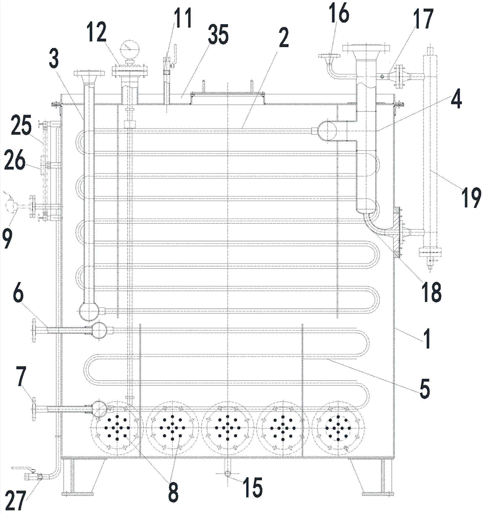
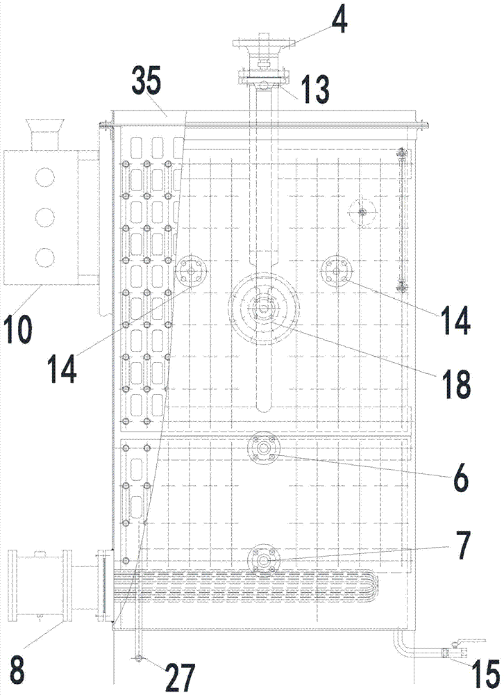
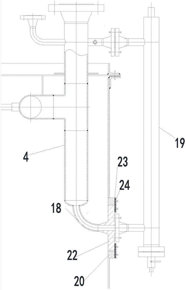
[0047] Such as Figure 1~5 As shown, the ultra-high-purity gas heat exchanger includes a shell 1, and the shell 1 is filled with water. The left heat exchange tube support fixing plate and the right heat exchange tube support fixing plate are respectively arranged on the left and right sides of the shell 1, and the left heat exchange tube is supported and fixed. The ammonia circulation coil assembly 2 is arranged between the plate and the right heat exchange tube support fixing plate, the bottom inlet of the ammonia circulation coil assembly 2 is connected to the feed pipe 3, and the top outlet of the ammonia circulation coil assembly 2 is connected to the discharge pipe 4 A hot water circulation coil assembly 5 is arranged below the ammonia circulation coil assembly 2, the upper end of the hot water circulation coil assembly 5 is a hot water inlet 6, and the lower end of the hot water circulation coil assembly 5 is a hot water outlet 7, in this embodiment The hot water inlet ...

Embodiment 2

[0067] The difference between this embodiment and Embodiment 1 is that there are 6 groups of plug-in electric heaters 8 in this embodiment, and they are arranged in an isosceles triangle shape. and the lower semicircle isolation cover 29, the upper semicircle isolation cover 28 and the lower semicircle isolation cover 29 are evenly provided with a number of through holes 30, the horizontal distance between the inner end of the plug-in electric heater 8 and the inner surface of the shell 1 is 130-150 mm, and the shell 1 An insulating layer 35 is provided on the outer surface.

[0068] The plug-in electric heaters 8 in the step (4) are 6 groups and arranged in an isosceles triangle; when the collected temperature is lower than 30°C, the PID controller controls 6 groups of plug-in electric heaters after calculation 8. Simultaneous heating work; when the collected temperature is between 30°C and 60°C, the PID controller performs calculations to control the top 1 group in the middl...


PUM


Abstract

The invention discloses an ultra-high purity gas heat exchanger and an implementation method thereof. The ultra-high purity gas heat exchanger comprises a shell filled with water inside, a left heat exchange pipe supporting and fixing plate, a right heat exchange pipe supporting and fixing plate, an ammonia circulation coil component, a feed pipe, a discharge pipe, a hot-water circulation coil component, a plurality of plug-in electric heaters and a thermalcouple. A hot-water inlet is formed in the upper end of the hot-water circulation coil component, a hot-water outlet is formed in the lower end of the hot-water circulation coil component, the thermalcouple is connected with a PID (piping and instruments diagram) controller in an explosion-proof tank on the outer surface of the shell, and the PID controller is connected with the plug-in electric heaters. The invention further discloses an implementation method of the Ultra-high purity gas heat exchanger. The ultra-high purity gas heat exchanger and the implementation method thereof have the advantages of simple structure, low cost and capability of being operated for a long time in succession, evaporation is quite stable, electrical heating and hot water of waste heat are combined for heating, energy conservation and environment protection are achieved and the like.

Description

technical field [0001] The invention relates to liquid vaporization technology, in particular to an ultra-high-purity gas heat exchanger and its realization method. Background technique [0002] Ultra-high-purity gas refers to a gas with a purity of less than one part per billion of oxygen. Ultra-high-purity gas plays a huge role in various fields such as the electronics industry, petrochemical industry, medicine, and national defense. The application fields are mainly in integrated circuit manufacturing, new electronic Components and other fields. Based on the importance of ultra-high-purity gases in the electronics industry and the restraint of cutting-edge technologies in the world, my country clearly supports the research and industrialization of domestic ultra-high-purity gases. [0003] In the prior art, the preparation of ultra-high-purity gas is generally realized by distillation towers. Distillation towers are divided according to the number, such as single tower c...

Claims


Application Information

Patent Timeline
Patent Type & Authority Applications(China)
IPC IPC(8): F24H7/04F24H9/18F24H9/20F24H9/00
Inventor 俞世桥厉磊磊蒋美卿
Owner ZHEJIANG KIN SHINE TECH
Why Eureka
Try Eureka