Radiating tube of oil radiator and production method thereof

A technology of oil radiator and production method, applied in the direction of heat exchanger shell, tubular element, heat exchange equipment, etc., can solve the problems of reducing performance and service life of radiator, high working pressure of hydraulic system, short service life, etc. Achieve the effect of reducing material cost, large heat dissipation and good versatility

Inactive Publication Date: 2014-07-16
YANTAI FUNAIKE RADIATOR
View PDF0 Cites 2 Cited by
  • Summary
  • Abstract
  • Description
  • Claims
  • Application Information

AI Technical Summary

Problems solved by technology

[0002] The hydraulic system is the main working part of construction machinery, and the oil radiator cooling pipe is an important part of the cooling system of the hydraulic system. The high-temperature hydraulic oil enters the radiator cooling pipe after being buffered by the radiator oil chamber, and then enters the hydraulic system for circulation after cooling The working pressure of the hydraulic system is relatively high. The existing oil radiator cooling pipes are generally made of steel pipes, cold-drawn pipes, and combined plate-fin structures. The disadvantages are poor pressure resistance, low strength, short service life, thick materials, The mechanical strength is low, and it is easy to burst under the condition of bearing a large force, resulting in water leakage of the heat dissipation pipe, reducing the performance and service life of the heat sink

Method used


Image

  • Radiating tube of oil radiator and production method thereof
  • Radiating tube of oil radiator and production method thereof
  • Radiating tube of oil radiator and production method thereof

Examples


Embodiment 1

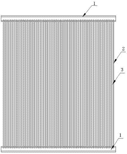
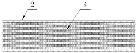
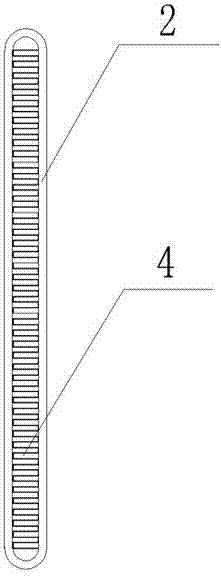
[0014] Embodiment 1, a kind of heat dissipation pipe of oil radiator, refer to figure 1 , figure 2 , the two ends of the heat dissipation pipe 2 are clamped on the main piece 1 and put into a continuous brazing furnace for nitrogen protection brazing to form a whole. The heat dissipation belt 3 is installed between the two heat dissipation pipes 2, and fins are installed in the heat dissipation pipe 2. 4. The fins 4 are in contact with the inner wall of the heat dissipation pipe 2, which constitutes a structure of the present invention;

[0015] The heat dissipation pipes of the above-mentioned oil radiators are produced by the following method: first, the fins 4 are installed in the heat dissipation pipes 2, and then the heat dissipation pipes 2 and the heat dissipation strips 3 are laid out in sequence, and a heat dissipation strip 3 is laid in sequence, and a heat dissipation pipe is laid on the front and back respectively. 2. Arrange neatly on the assembly table, use a f...

Embodiment 2

[0016] Embodiment 2, a kind of heat dissipation pipe of oil radiator, refer to figure 1 , figure 2 , image 3 , on the basis of Example 1, the radiating pipe 2 is in the shape of an oval flat tube, and the radiating pipe 2 is formed by high-frequency welding of an aluminum sheet without a composite layer, and the wall thickness is between 0.5mm and 1.0mm. Example 1 is exactly the same.


PUM

PropertyMeasurementUnit
thicknessaaaaaaaaaa

Abstract

The invention discloses a radiating tube of an oil radiator and a production method thereof; the radiating tube mainly consists of main sheets, radiating pipes and radiating belts, wherein fins are arranged in the radiating pipes, each radiating pipe is in an oval flat pipe shape which is formed by performing high-frequency welding on an aluminum sheet which is not provided with a composition layer, and the wall thickness is in a range of 0.5mm to 1.0mm; the method comprises the steps of: sequentially tiling the radiating pipes and the radiating belts, distributing the radiating pipes and the radiating belts alternatively, stacking orderly on an assembling table, aligning the main sheet hole with the radiating pipe by a plate and tapping the clamp part, turning over a core body, installing the main sheet on the other side by using the same method, fixing the radiating pipe and the main sheet which have been connected by a fixture, and then placing into a continuous brazing furnace to perform brazing under the protection of nitrogen; the radiating tube has the characteristics of higher strength, light and thin materials, easiness in installation and good universality and can be widely applied to the fields of engineering machines, heavy duty trucks, special vehicles and the like.

Description

technical field [0001] The invention belongs to the technical field of radiating pipes for engineering machinery, and in particular relates to a radiating pipe for an oil radiator and a production method thereof. Background technique [0002] The hydraulic system is the main working part of construction machinery, and the oil radiator cooling pipe is an important part of the cooling system of the hydraulic system. The high-temperature hydraulic oil enters the radiator cooling pipe after being buffered by the radiator oil chamber, and then enters the hydraulic system for circulation after cooling The working pressure of the hydraulic system is relatively high. The existing oil radiator cooling pipes are generally made of steel pipes, cold-drawn pipes, and combined plate-fin structures. The disadvantages are poor pressure resistance, low strength, short service life, thick materials, The mechanical strength is low, and it is easy to burst when subjected to a large force, resul...

Claims


Application Information

Patent Timeline
Patent Type & Authority Applications(China)
IPC IPC(8): F28F1/42F28F9/18F28F21/08B23K1/008B23K1/20
Inventor 王高佐鲍丽艳
Owner YANTAI FUNAIKE RADIATOR
Why Eureka
Try Eureka