Built-in high-temperature wireless pressure sensor

A pressure sensor and sensor technology, which is applied in the measurement of fluid pressure using capacitance change, and the measurement of force by measuring the frequency change of a stressed vibration element, can solve the problems of difficult application temperature exceeding 600 ℃ and complex process.

Inactive Publication Date: 2014-07-16
XIAMEN UNIV
View PDF6 Cites 13 Cited by
  • Summary
  • Abstract
  • Description
  • Claims
  • Application Information

AI Technical Summary

Problems solved by technology

However, in the wireless pressure sensors reported so far, the RLC resonant circuit is basically made of metal lead wire technology, and its application temperature is difficult to exceed 600°C
US Patent No. 7478562B2 discloses a high temperature LC pressure sensor, the disclosed sensor is SiC-SiO 2 -SiC three-layer structure, the upper plate of the capacitor and the lower plate of the capacitor are made on the lower surface of the upper SiC and the upper surface of the lower SiC respectively, so that the parallel plate capacitor C is embedded in the three-layer structure, and the inductor L is made at the bottom of the lower SiC, It is connected with the parallel plate capacitor C through a through hole, and the process is complicated

Method used


Image

  • Built-in high-temperature wireless pressure sensor
  • Built-in high-temperature wireless pressure sensor
  • Built-in high-temperature wireless pressure sensor

Examples


Embodiment Construction

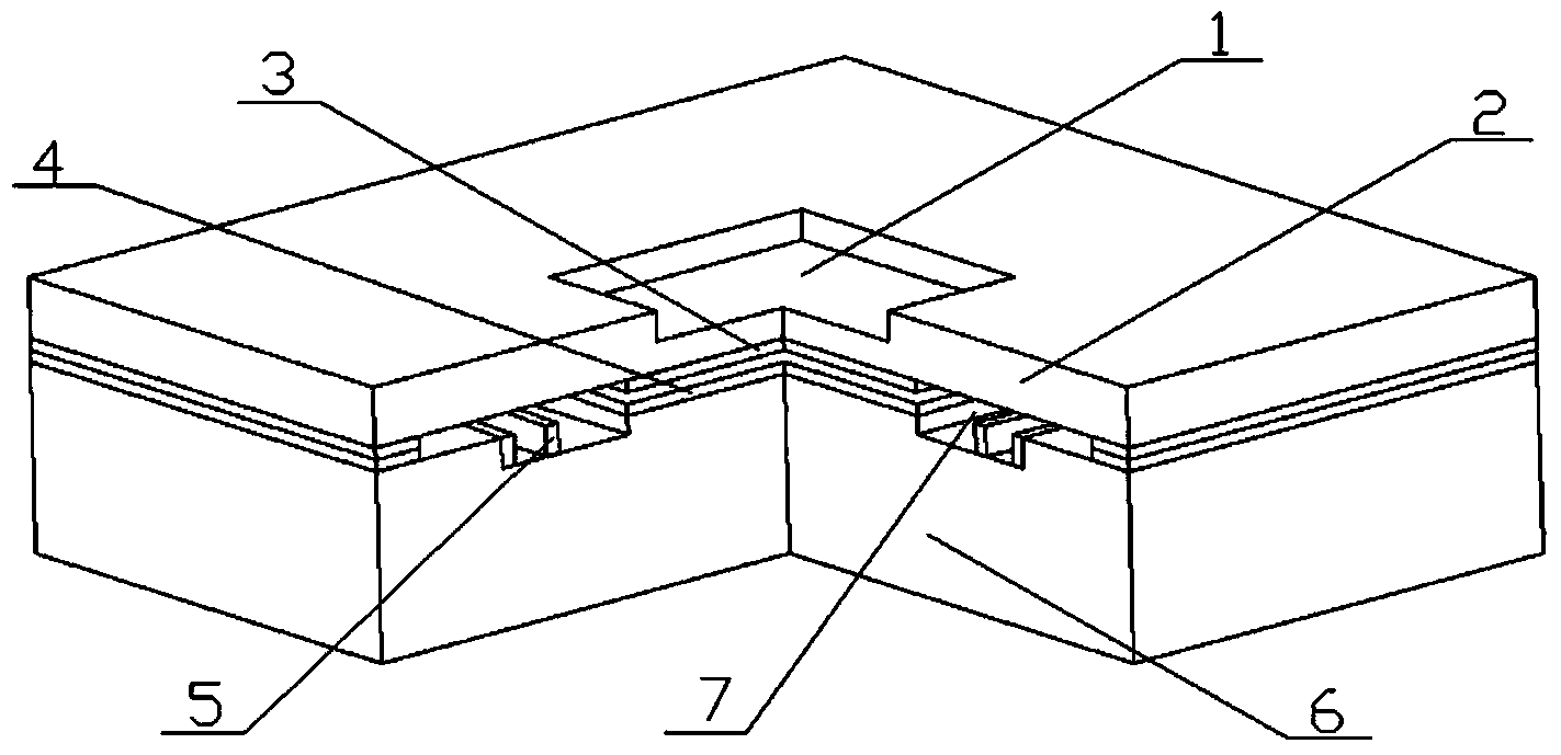
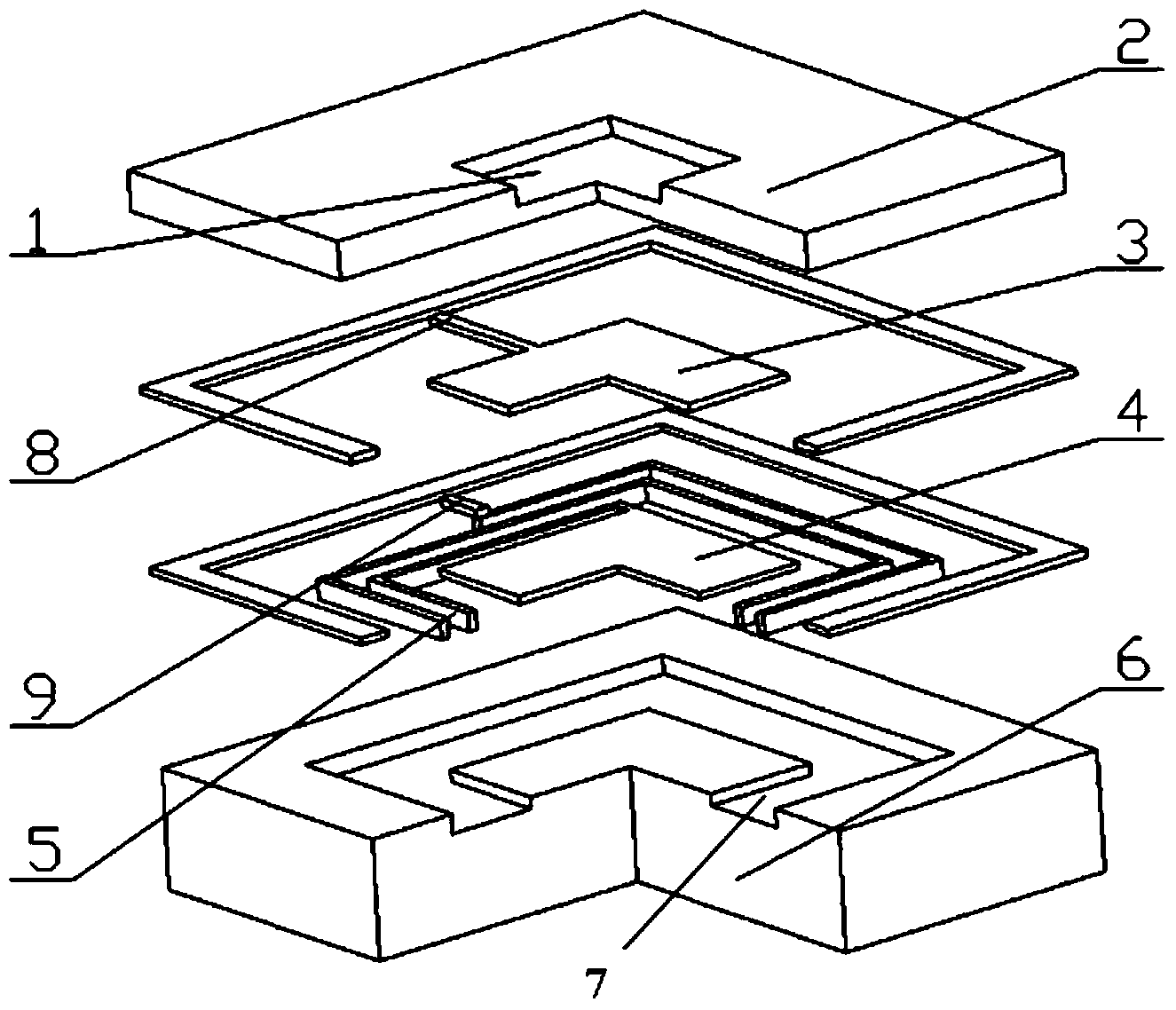
[0022] see Figure 1~4 , the embodiment of the present invention is provided with a pressure sensitive membrane 1 , a sensor upper cover plate 2 , a capacitor upper plate 3 , a capacitor lower plate 4 , an inductance coil 5 , a sensor base 6 and a pressure reference cavity 7 . The sensor upper cover plate 2 is made of SiC sheet, a square groove is opened on the sensor upper cover plate to form a pressure sensitive film 1, and a capacitor upper plate 3 is made on the back of the sensor upper cover plate 2; the sensor base 6 Made of SiC sheet, the sensor base 6 is provided with a return-shaped groove, the capacitor lower plate 4 and the inductance coil 5 are made on the sensor base 6, and the upper surface of the capacitor lower plate 4 is flush with the upper surface of the inductance coil 5 , and the inductance coil 5 is made in the return-shaped groove to increase the thickness of the inductance coil 5; the capacitor upper plate 3, the capacitor lower plate 4 and the inductan...


PUM

PropertyMeasurementUnit
Sensitivityaaaaaaaaaa
thicknessaaaaaaaaaa
thicknessaaaaaaaaaa

Abstract

The invention relates to a pressure sensor, in particular to a built-in high-temperature wireless pressure sensor. The built-in high-temperature wireless pressure sensor is provided with a pressure sensitive film, a sensor upper covering plate, a capacitor upper counter electrode, a capacitor lower counter electrode, an inductance coil, a sensor base and a pressure reference cavity, wherein a square groove is formed in the sensor upper covering plate to form the pressure sensitive film, the capacitor upper counter electrode is manufactured on the back surface of the sensor upper covering plate, a groove shaped like a Chinese character 'hui' is formed in the sensor base, the capacitor lower counter electrode and the inductance coil are manufactured on the sensor base, the upper surface of the capacitor lower counter electrode is flush with the upper surface of the inductance coil, and the inductance coil is manufactured in the groove shaped like the Chinese character 'hui'. The capacitor upper counter electrode, the capacitor lower counter electrode and the inductance coil are all made of silicon doped with metal, the capacitor upper counter electrode and the capacitor lower counter electrode form a parallel plate capacitor, the capacitor upper counter electrode and the inductance coil lead out wires at the upper layer and wires at the lower layer respectively, the sensor upper covering plate and the sensor base are bonded, the wires at the upper layer make tight contact with the wires at the lower layer, the capacitor upper counter electrode, the inductance coil and the capacitor lower counter electrode are connected in series to form a standard RLC loop, and the pressure reference cavity is formed.

Description

technical field [0001] The invention relates to a pressure sensor, in particular to an embedded high-temperature wireless pressure sensor. Background technique [0002] Pressure measurement under high temperature and extreme environment is one of the basic science and technologies that must be broken through and mastered in the fields of petrochemical production, aerospace, automotive electronics, national defense and military industry. As one of the main products of micro-electromechanical systems (MEMS), high-temperature-resistant pressure sensors have broad application requirements and prospects in the fields of industry and national defense. Specifically, it can be used in the industry for pressure detection and control of chemical reaction kettles, smelting towers, high-temperature oil wells, and turbine engines and internal combustion engines. In national defense and military, it can be used for attitude control of aerospace vehicles, flight control of high-speed airc...

Claims


Application Information

Patent Timeline
Patent Type & Authority Applications(China)
IPC IPC(8): G01L1/10G01L9/12
Inventor 王凌云周如海蔡建法郑成何勇陈丹儿
Owner XIAMEN UNIV
Why Eureka
Try Eureka