Cable connection device and method for circuit board ionic migration test

A cable connection and ion migration technology, applied to the casing of the measuring device, etc., can solve the problems of accelerated test cable consumption, insufficient consumption, inconvenient cleaning operation, etc., to eliminate the possibility of pollution, improve the utilization rate, and achieve good cleaning effect.

Active Publication Date: 2014-07-16
SHANGHAI MEADVILLE SCI & TECH
View PDF5 Cites 0 Cited by
  • Summary
  • Abstract
  • Description
  • Claims
  • Application Information

AI Technical Summary

Problems solved by technology

[0005] First, generally, a cable of 2 meters to several meters is required from the environmental test chamber to the test equipment outside the chamber. Such a long cable plus a connector makes it very inconvenient to operate when soldering the cable to the circuit board.
Especially after the soldering is completed, it is necessary to completely clean the flux residue on the circuit board. Such a long cable connected to the circuit board will cause the cleaning operation to be very inconvenient, and sometimes it will lead to incomplete cleaning and test failure.
[0006] Second, because the general ion migration test lasts for 100-1000 hours or even longer, the test cable is in the environmental test chamber. After several ion migration tests, the conductor part in the cable insulation, especially near the welding The dot part will also be corroded, which will lead to poor solderability of the conductor of the cable when welding next time, and it is very difficult to weld, so a long part of the cable at one end of the lead wire of the test cable has to be cut off to expose the conductor that has not been welded. The corroded cable conductor part will greatly speed up the consumption of the test cable. When the consumption is insufficient to connect the environmental test box to the test equipment outside the box and the environmental test box to the product to be tested inside the box, the cable can no longer be used. At this point the cable is about 2 meters or even longer
It is very cumbersome to re-make the cables connected to the ion mobility test system
[0007] Third, because the test cables need good insulation properties, they are relatively expensive. Generally, a set of ion mobility test system is equipped with only one set of test cables, so that if the next batch of samples needs to be tested, it must wait until the previous batch of tests is completed, and then Remove the test cable from its circuit board before soldering the next batch of circuit board samples, which will reduce the utilization rate of the test equipment
[0009] First, use stainless steel. Although stainless steel is corrosion-resistant, there will still be some slight corrosion after a very long test.
In addition, it is very difficult to clean the metal oxide stains on the inserts. These corrosion and stains may contaminate the test samples during the test.
[0010] Second, stainless steel is used. During the test, if the sample moves on the rack, it is easy to cause a short circuit of the test sample and form a false failure.
If the soldering point of the test sample is very close to the edge of the sample, it is easy to cause a short circuit between the soldering point and the socket when the socket is inserted, resulting in a false failure
[0011] Third, the stainless steel insert can only adjust the width in the width direction, and the applicable sample size range is relatively small
[0012] Fourth, when the sample is tested in the environmental test chamber, when the heat insulation performance of the chamber wall is deteriorated due to the defect or aging of the environmental chamber, the high-humidity air is easy to condense on the chamber wall and the top of the chamber. To the sample, it will cause the insulation resistance of the sample to drop or short circuit, which will lead to the failure of the test

Method used


Image

  • Cable connection device and method for circuit board ionic migration test
  • Cable connection device and method for circuit board ionic migration test
  • Cable connection device and method for circuit board ionic migration test

Examples


Embodiment Construction

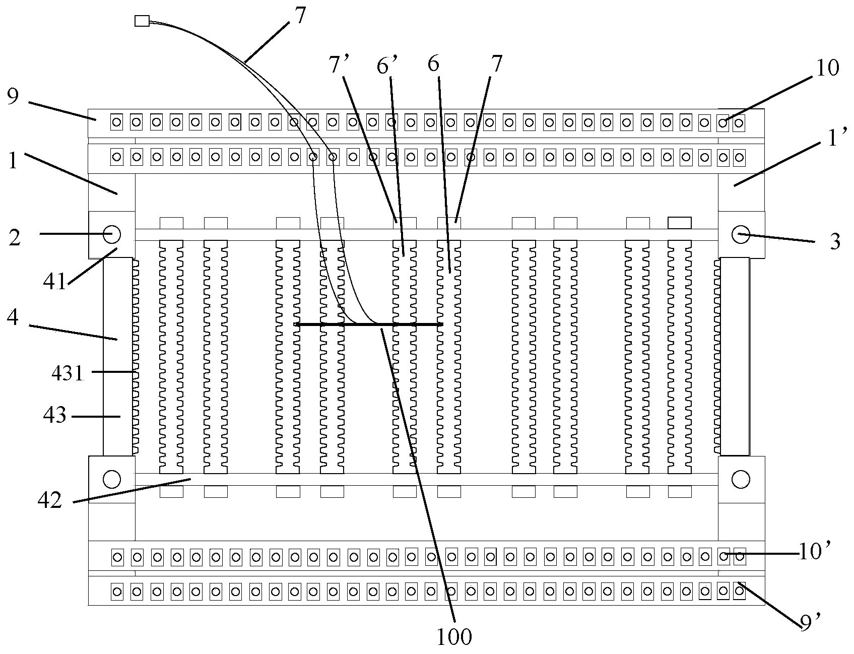
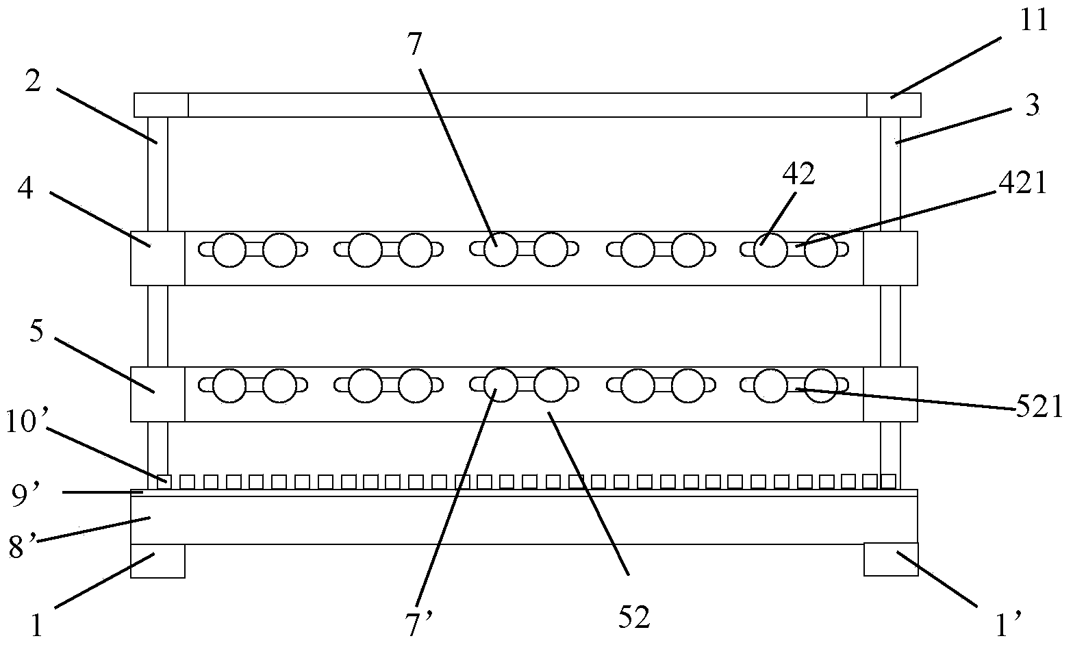
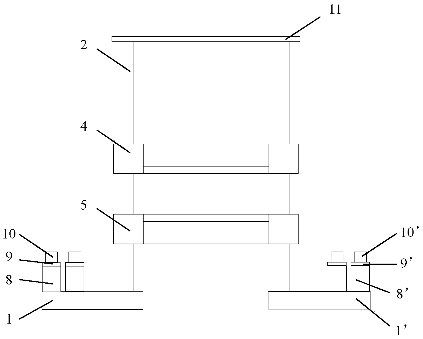
[0038] see Figure 1 ~ Figure 4, the cable connection device of the circuit board ion migration test of the present invention, it comprises, two fixed bottom plates 1,1 ', opposite arrangement; The two are arranged on the upper end surfaces of the opposite sides of the two fixed base plates 1, 1'; the upper and lower frames 4, 5 are rectangular frame structures, and their four corners are provided with the four columns 2, The column fixing blocks 41, 51 on the 3; the two long frame bars 42, 52 of the upper and lower frames 4, 5 (taking the long frame bars 42, 52 as an example, the same below) provide several guide grooves 421, 521 along the length direction A number of racks 6, 6', the two ends of which are respectively inserted into the guide grooves 421, 521 of the two long frame bars 42, 52 of the upper and lower frames 4, 5, and are locked by the fixing nuts 7, 7'; the upper and lower frames 4, 5 wide frame bar 43 (taking wide frame bar 43 as an example, the same below) h...


PUM


Abstract

The invention provides a cable connection device and method for a circuit board ionic migration test. The device comprises two fixed bottom plates which are opposite, four stand columns, an upper frame, a lower frame, a plurality of racks, at least two reinforcing plates, at least two terminal fixing plates, a plurality of terminals, and a top plate. The four stand columns are arranged on the upper end faces of opposite sides of the two fixed bottom plates respectively, stand column fixing blocks are arranged on four corners of the upper frame and four corners of the lower frame respectively, a plurality of guiding grooves are formed in the two long edge bars of the upper frame in the length direction and the two long edge bars of the lower frame in the length direction respectively, the two ends of each rack are inserted to the guiding grooves in the two long edge bars of the upper frame and the two long edge bars of the lower frame respectively and are locked by retaining nuts, tooth grooves are formed in the inner side faces of wide edge bars of the upper frame and wide edge bars of the lower frame respectively, the two reinforcing plates are arranged on the upper end faces of the outer sides of the two fixed bottom plates, the two terminal fixing plates are arranged on the upper end faces of the reinforcing plates respectively, the terminals are arranged in the length direction of the terminal fixing plates, the top plate is rectangular, and fixing sleeves or grooves capable of being fixed on the four stand columns in a sleeved mode are arranged on the four corners of the lower end face of the top plate. Cleaning is convenient after cables are welded, consumption of cables in the ionic migration test is low, the system utilization rate of the ionic migration test is high, and samples are not prone to pollution and short circuit in the test process.

Description

technical field [0001] The invention relates to a circuit board testing method, in particular to a cable connection device and a connection method for the circuit board ion migration test. Background technique [0002] In the ion migration test of the circuit board, it is necessary to place the circuit board in a high-temperature and high-humidity environmental test chamber, and weld the cable on the circuit board, and lead it to the relevant testing equipment outside the environmental test chamber, so as to test the circuit board on the circuit board. Apply a bias voltage that promotes ion migration and perform an insulation resistance test. [0003] The cable connection method in the existing ion mobility test is to use a test cable, one end of the test cable is a connector, and the other end is a wire. During the test, the ion mobility test system and the test sample are directly connected, that is, the test cable The connector at one end is connected to the connector of...

Claims


Application Information

Patent Timeline
Patent Type & Authority Applications(China)
IPC IPC(8): G01R1/04
Inventor 方军良
Owner SHANGHAI MEADVILLE SCI & TECH
Why Eureka
Try Eureka