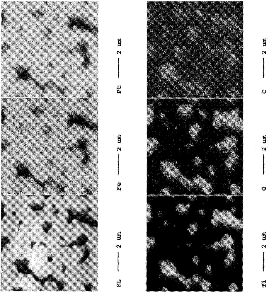
Fe-Pt-based sputtering target in which C particles are dispersed
A sputtering target and particle technology, which is applied in the field of sputtering targets, can solve problems such as shedding, and achieve the effect of reducing the amount of powder particles
- Summary
- Abstract
- Description
- Claims
- Application Information
AI Technical Summary
Problems solved by technology
Method used
Image
Examples
Embodiment 1
[0059] Fe powder with an average particle size of 3 μm, Pt powder with an average particle size of 3 μm, C powder with an average particle size of 1 μm, and TiO with an average particle size of 1 μm were prepared as raw material powders. 2 powder. As C powder, commercially available amorphous carbon was used.
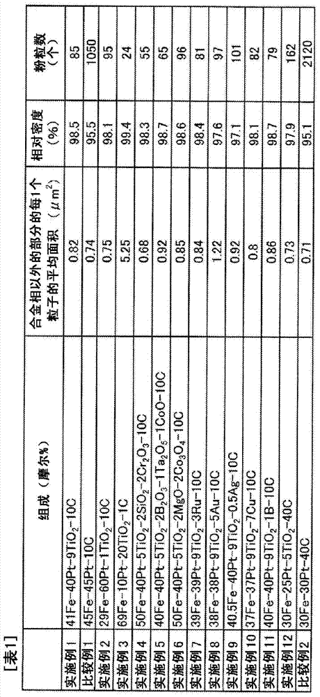
[0060] to become 41Fe-40Pt-9TiO 2 These powders were weighed so that the total weight may be 2600 g at -10C (mol %).
[0061] Next, the weighed powder was enclosed in a 10-liter ball mill tank together with titanium dioxide balls as a grinding medium, and rotated for 4 hours to perform mixing and grinding. Then, the mixed powder taken out from the ball mill was filled into a carbon mold and hot-pressed.
[0062] The hot pressing conditions were set to vacuum atmosphere, heating rate 300° C. / hour, holding temperature 1200° C., holding time 2 hours, and pressurized at 30 MPa from the start of heating to the end of holding. After the hold is over, let it cool naturally...
Embodiment 2
[0069] Fe powder with an average particle size of 3 μm, Pt powder with an average particle size of 3 μm, C powder with an average particle size of 1 μm, and TiO with an average particle size of 1 μm were prepared as raw material powders. 2 powder. As C powder, commercially available amorphous carbon was used. to become 29Fe-60Pt-1TiO 2 These powders were weighed so that the total weight may be 2600 g at -10C (mol %).
[0070] Next, the weighed powder was enclosed in a 10-liter ball mill tank together with titanium dioxide balls as a grinding medium, and rotated for 4 hours to perform mixing and grinding. Then, the mixed powder taken out from the ball mill was filled into a carbon mold and hot-pressed.
[0071] The hot pressing conditions were set to vacuum atmosphere, heating rate 300° C. / hour, holding temperature 1200° C., holding time 2 hours, and pressurized at 30 MPa from the start of heating to the end of holding. After the hold is over, let it cool naturally in the c...
Embodiment 3
[0078] Fe powder with an average particle size of 3 μm, Pt powder with an average particle size of 3 μm, C powder with an average particle size of 1 μm, and TiO with an average particle size of 1 μm were prepared as raw material powders. 2 powder. As C powder, commercially available amorphous carbon was used.
[0079] to become 69Fe-10Pt-20TiO 2 These powders were weighed so that the total weight was 2600 g at -1C (mol %).
[0080]Next, the weighed powder was enclosed in a 10-liter ball mill tank together with titanium dioxide balls as a grinding medium, and rotated for 4 hours to perform mixing and grinding. Then, the mixed powder taken out from the ball mill was filled into a carbon mold and hot-pressed.
[0081] The hot pressing conditions were set to vacuum atmosphere, heating rate 300° C. / hour, holding temperature 1100° C., holding time 2 hours, and pressurized at 30 MPa from the start of heating to the end of holding. After the hold is over, let it cool naturally in ...
PUM
| Property | Measurement | Unit |
|---|---|---|
| particle diameter | aaaaa | aaaaa |
Abstract
Description
Claims
Application Information
 - R&D
- Intellectual Property
- Life Sciences
- Materials
- Tech Scout
- Unparalleled Data Quality
- Higher Quality Content
- 60% Fewer Hallucinations
Browse by: Latest US Patents, China's latest patents, Technical Efficacy Thesaurus, Application Domain, Technology Topic, Popular Technical Reports.
© 2025 PatSnap. All rights reserved.Legal|Privacy policy|Modern Slavery Act Transparency Statement|Sitemap|About US| Contact US: help@patsnap.com


