Mud separation equipment

A mud separation and equipment technology, applied in the direction of dehydration/drying/thickened sludge treatment, etc., can solve the problems of large floor area of ​​the mixing tank, high transportation cost, difficult sedimentation and stratification, etc., and achieve safe and environmentally friendly use and high work efficiency High, good separation effect

Inactive Publication Date: 2014-07-23
赵建寅 +2
View PDF5 Cites 9 Cited by
  • Summary
  • Abstract
  • Description
  • Claims
  • Application Information

AI Technical Summary

Problems solved by technology

[0002] Mud has a certain viscosity, and it is difficult to settle and stratify after standing for a long time. At present, the treatment method for mud in the industry is to use the mixing tank, pour the mud and flocculant into the mixing tank for stirring, and promote the sedimentation and stratification of the mud. Finally, the slurry in the upper layer is pumped away, and the sludge deposited at the bottom of the tank is taken out. The disadvantage is that the stirring tank occupies a large area, the sedimentation time is long, and it cannot be operated continuously. Moreover, the sludge separated by this method has a high water content, and the sludge The weight is heavy. When transferring the sludge, in order to prevent the water in the sludge from being scattered

Method used


Image

  • Mud separation equipment
  • Mud separation equipment

Examples


Embodiment Construction

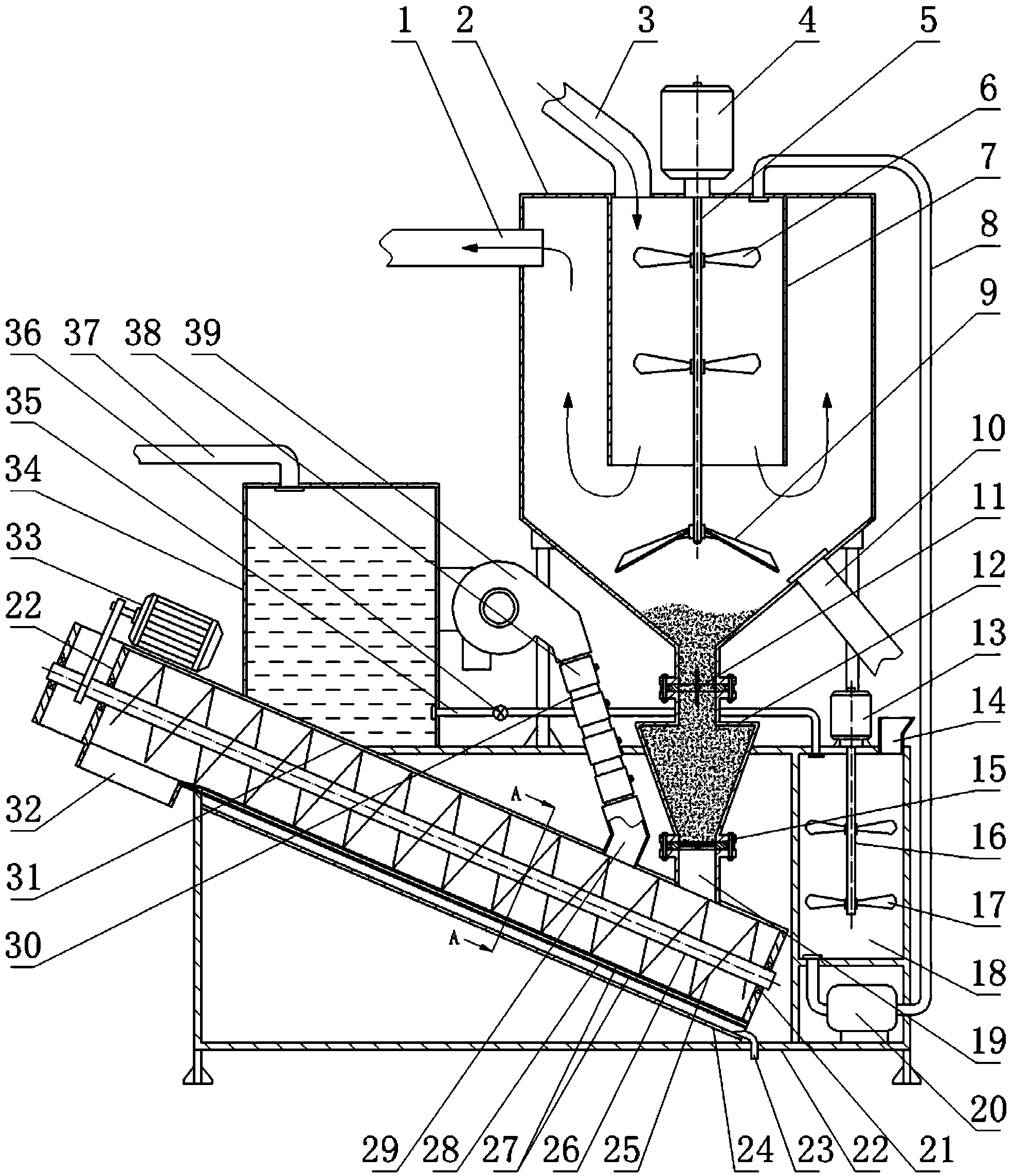
[0010] Slurry separation equipment, a separation device, a conveying and drying device and a drug supply device are housed on the frame 22, and the separation device has a stirring tank 2 and a slurry storage bucket 12, and the tank top of the stirring tank is provided with a slurry inlet pipe 3, a slurry supply Medicine tube 8 and stirring motor 4. In the stirring tank, multiple sets of stirring blades 6 are installed on the shaft connected to the stirring motor shaft 5. The stirring blades at the lower part are also called pressing blades 9. The blades can cut and lift the water flow and offset the The downward flow from the top makes the water flow at the bottom of the mixing tank tend to be stable, which is conducive to the sedimentation of the sludge, and forms a certain suction force under the blades, so that the sludge deposited from the four walls of the mixing tank is concentrated on the conical bottom of the mixing tank. At the slurry outlet; the upper stirring blade ...


PUM


Abstract

The invention provides mud separation equipment. A separation device, a conveying baking device and a chemical supply device are arranged on a frame; the separation device is provided with a stirring tank and a mud storage hopper; the lower part of the stirring tank is conical; a first valve is arranged on a connecting pipe between the mud outlet of the conical bottom and the feed port of the mud storage hopper, and a second valve is arranged at the discharge port of the mud storage hopper; a U-shaped groove is formed in the conveying baking device, a helical blade is arranged in the U-shaped groove, a wet material port and an air inlet are formed in the lower end of the U-shaped groove, the wet material port is connected with the second valve, and the air inlet is connected with an air blower by virtue of an air pipe; an electric jacket is arranged on the air pipe; a water tank of the chemical supply device is communicated with a chemical tank through a water pipe; the chemical outlet pipe of the chemical tank is communicated with the chemical supply pipe by virtue of a water pump. Sludge deposited at the bottom of the tank is conveyed to the conveying baking device due to opening-closing coordination of the two valves of the mud storage hopper, and residual moisture in the sludge is baked by the conveying baking device, so that the discharged sludge is basically dehydrated and dried. The mud separation equipment has the advantages of good separation effect, small floor area, high working efficiency, and safety and environmental friendliness in use.

Description

technical field [0001] The invention provides a mud separation device, which belongs to the field of environmental protection equipment. technical background [0002] Mud has a certain viscosity, and it is difficult to settle and stratify after standing for a long time. At present, the treatment method for mud in the industry is to use the mixing tank to pour the mud and flocculant into the mixing tank for stirring, so as to promote the sedimentation and stratification of the mud. Finally, the slurry in the upper layer is pumped away, and the sludge deposited at the bottom of the tank is taken out. The disadvantages are that the mixing tank occupies a large area, the sedimentation time is long, and it cannot be operated continuously. Moreover, the sludge separated by this method has a high water content, and the sludge The weight is heavy. When transferring the sludge, in order to prevent the water in the sludge from being scattered on the road and causing pollution to the r...

Claims


Application Information

Patent Timeline
IPC IPC(8): C02F11/12C02F11/14
Inventor 赵建寅赵山峰赵玲丽
Owner 赵建寅
Why Eureka
Try Eureka