A fiber grating differential strain gauge and its production and use method
A fiber grating and manufacturing method technology, applied in the direction of optical devices, measuring devices, instruments, etc., can solve the problems of temperature and strain cross-sensitivity, inconvenient engineering construction, and affecting the accuracy of measurement, so as to eliminate accuracy and consistency performance, elimination of chirp phenomenon, and easy operation
- Summary
- Abstract
- Description
- Claims
- Application Information
AI Technical Summary
Problems solved by technology
Method used
Image
Examples
Embodiment 1
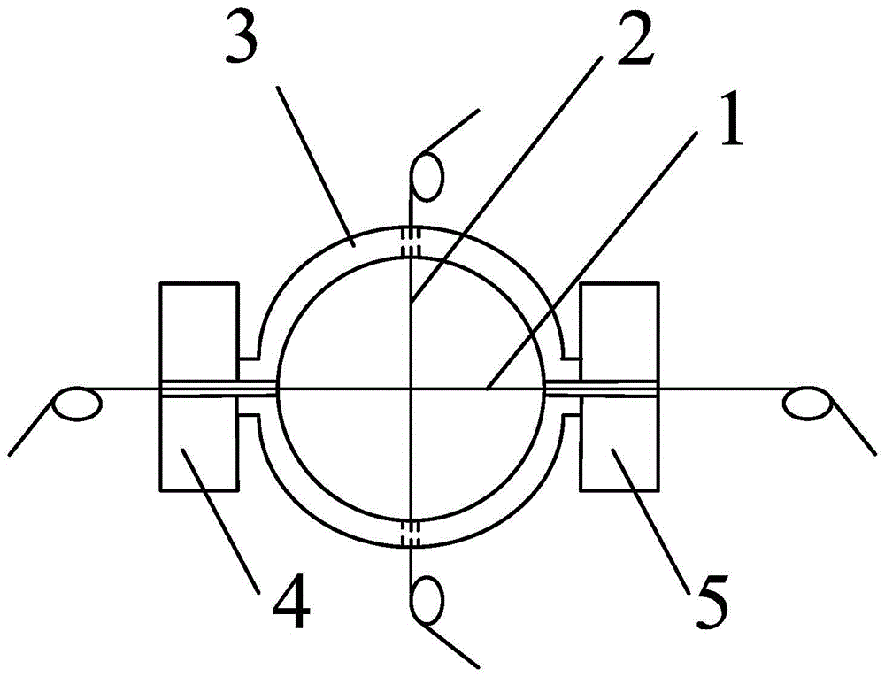
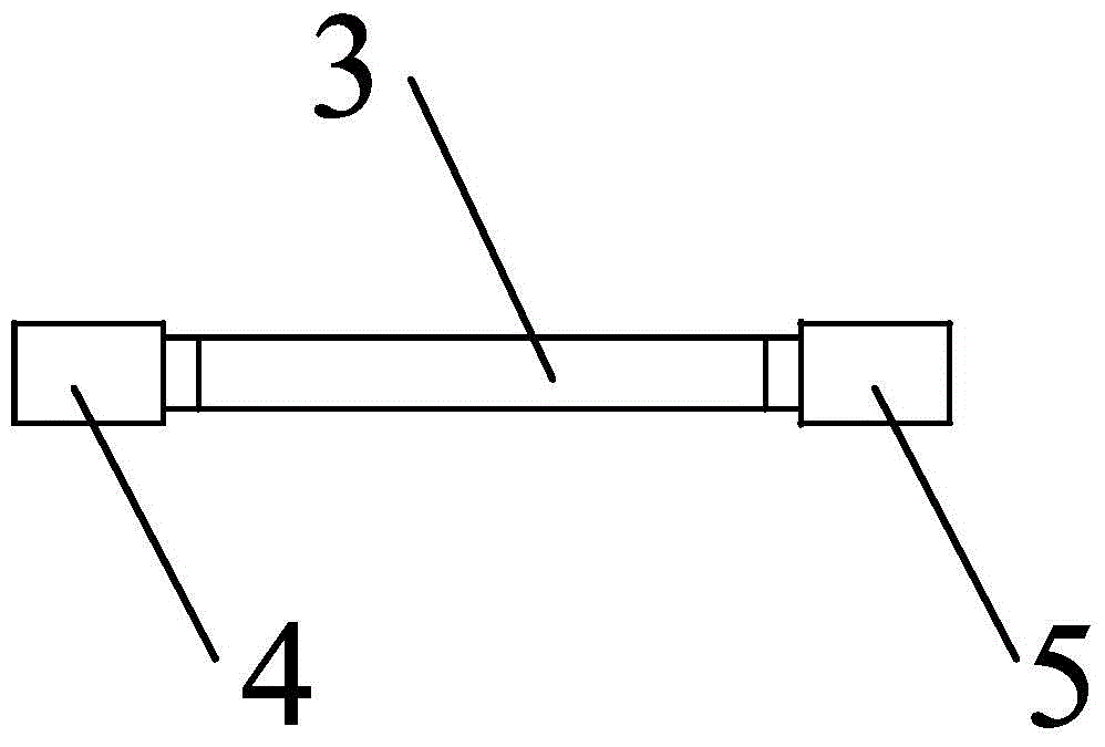
[0025] figure 1 It is a structural schematic diagram of Embodiment 1 of the present invention, figure 2 for figure 1 The top view of , which includes the first fiber grating 1, the second fiber grating 2, the elastic body and the mounting arm, the elastic body is a ring-shaped deformation body 3 (the steel ring-shaped deformation body is used in this embodiment) wherein the two ends of the first fiber grating 1 are pasted on one side of the annular deformation body 3, and the two ends of the second fiber grating 2 are pasted on the other side of the annular deformation body 3, the first fiber grating 1 and the second optical fiber The gratings 2 are perpendicular to each other, and the gratings of both pass through the central axis of the annular deformation body 3 and do not touch; the mounting arms are fixed on both sides of the annular deformation body 3 and are divided into the first mounting arm 4 and the second mounting arm 4. Two installation arms 5, and in the same ...
Embodiment 2
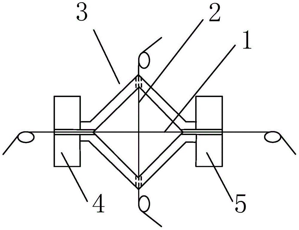
[0042] The structure and principle of this embodiment are basically the same as those of Embodiment 1, the difference is that the elastic body is a hollow regular polygon deformed body.
[0043] Take the regular quadrilateral, that is, the square deformed body as an example, such as image 3 and Figure 4 As shown, it includes a first fiber grating 1, a second fiber grating 2, an elastic body, a first mounting arm 4 and a second mounting arm 5, and the elastic body is a square deformation body 3; the installation method and embodiment of this embodiment One is installed in the same way. Fix this embodiment on the monitored body through the mounting arm, and use the following formula to obtain the variation of the grating center wavelength differential of the fiber grating differential strain gauge:
[0044] Δd = ( 1 - P e ) ...
PUM
 Abstract
Description
Claims
Application Information
 - R&D
- Intellectual Property
- Life Sciences
- Materials
- Tech Scout
- Unparalleled Data Quality
- Higher Quality Content
- 60% Fewer Hallucinations
Browse by: Latest US Patents, China's latest patents, Technical Efficacy Thesaurus, Application Domain, Technology Topic, Popular Technical Reports.
© 2025 PatSnap. All rights reserved.Legal|Privacy policy|Modern Slavery Act Transparency Statement|Sitemap|About US| Contact US: help@patsnap.com


