A Method for Measuring Topological Charge Number of Vortex Beam Based on Improved Mach-Zehnder Interferometer

A vortex beam and topological charge technology, applied in the field of digital holography, can solve the problems of low reliability, poor stability, high cost, etc.

Inactive Publication Date: 2017-06-13
KUNMING UNIV OF SCI & TECH
View PDF5 Cites 0 Cited by
  • Summary
  • Abstract
  • Description
  • Claims
  • Application Information

AI Technical Summary

Problems solved by technology

[0008] The invention provides a device and method for measuring the topological charge number of a vortex beam based on an improved Mach-Zehnder interferometer, which is used to solve the problem that the current method for measuring the topological charge number of a vortex beam requires specific instruments or equipment, and these devices require high Cost or special preparation is required, or the existing assay methods are complex in operation, poor in stability, and low in reliability

Method used


Image

  • A Method for Measuring Topological Charge Number of Vortex Beam Based on Improved Mach-Zehnder Interferometer
  • A Method for Measuring Topological Charge Number of Vortex Beam Based on Improved Mach-Zehnder Interferometer
  • A Method for Measuring Topological Charge Number of Vortex Beam Based on Improved Mach-Zehnder Interferometer

Examples


Embodiment 1

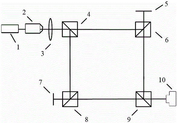
[0059] Embodiment 1: as Figure 1-8 As shown, a device for measuring the topological charge number of a vortex beam based on an improved Mach-Zehnder interferometer includes a semiconductor laser 1, a microscopic objective lens spatial filter 2, a collimator lens 3, a beam splitting prism I 4, a plane mirror 5, Dichroic prism II6, spatial light modulator 7, dichroic prism III8, dichroic prism IV9, and photoelectric coupler 10; wherein the distance between the semiconductor laser 1 and the spatial filter 2 of the microscopic objective lens is 0.15m, and the front focal plane of the collimating lens 3 is located exactly at the The exit pupil position of the micro-objective lens spatial filter 2, the dichroic prism I4 is 0.08m away from the collimating lens 3, the dichroic prism I4 and the dichroic prism II6 are on the same horizontal line, the dichroic prism I4 and the dichroic prism III8 are on the same vertical line, Dichroic prism III8 and dichroic prism IV9 are on the same h...

Embodiment 2

[0074] Embodiment 2: as Figure 1-8 As shown, a device for measuring the topological charge number of a vortex beam based on an improved Mach-Zehnder interferometer includes a semiconductor laser 1, a microscopic objective lens spatial filter 2, a collimator lens 3, a beam splitting prism I 4, a plane mirror 5, Dichroic prism II6, spatial light modulator 7, dichroic prism III8, dichroic prism IV9 and photoelectric coupler 10; wherein the distance between the semiconductor laser 1 and the spatial filter 2 of the microscopic objective lens is 0.16m, and the front focal plane of the collimating lens 3 is exactly located at the The exit pupil position of the micro-objective lens spatial filter 2, the dichroic prism I4 is 0.10m away from the collimator lens 3, the dichroic prism I4 and the dichroic prism II6 are on the same horizontal line, the dichroic prism I4 and the dichroic prism III8 are on the same vertical line, Dichroic prism III8 and dichroic prism IV9 are on the same hor...

Embodiment 3

[0089] Embodiment 3: as Figure 1-8 As shown, a device for measuring the topological charge number of a vortex beam based on an improved Mach-Zehnder interferometer includes a semiconductor laser 1, a microscopic objective lens spatial filter 2, a collimator lens 3, a beam splitting prism I 4, a plane mirror 5, Dichroic prism II6, spatial light modulator 7, dichroic prism III8, dichroic prism IV9, and photoelectric coupler 10; wherein the distance between the semiconductor laser 1 and the spatial filter 2 of the microscopic objective lens is 0.2m, and the front focal plane of the collimator lens 3 is exactly located at the The exit pupil position of the micro-objective lens spatial filter 2, the dichroic prism I4 is 0.15m away from the collimator lens 3, the dichroic prism I4 and the dichroic prism II6 are on the same horizontal line, the dichroic prism I4 and the dichroic prism III8 are on the same vertical line, Dichroic prism III8 and dichroic prism IV9 are on the same hori...


PUM


Abstract

The invention relates to a device and method for detecting the topological charge number of vortex beams based on an improved Mach-Zehnder interferometer, and belongs to the technical field of digital holography. The device comprises a semiconductor laser unit, a microscope objective spatial fiber, a collimating lens, a beam splitter prism I, a plane mirror, a beam splitter prism II, a spatial light modulator, a beam splitter prism III, a beam splitter prism IV and a photoelectric coupled device. According to the method, one arm of the device is used for generating the vortex beams to be used as object light, the other arm of the device is used for generating the vortex beams to be used as reference light, the holographic interferometry principle is used for recording the wave front phase information of the vortex beams in an interference fringe mode, phase distribution is digitally reconstructed in the later period, and the topological charge number of the vortex beams can be obtained according to the reconstructed phase distribution in accordance with the definition of the vortex beams. The device and method solve the problem that at present, specific instruments or equipment is needed in the method for detecting the topological charge number of the vortex beams, or an existing detecting method is complex to operate, poor in stability and low in reliability.

Description

technical field [0001] The invention relates to a device and method for measuring the topological charge number of a vortex beam based on an improved Mach-Zehnder interferometer, and belongs to the technical field of digital holography. Background technique [0002] Digital holography technology is the product of the combination of computer technology and traditional optical holography. Using digital recording and reproduction methods, the amplitude information and phase information of the object can be obtained more conveniently. The phase information is an important parameter for restoring the three-dimensional shape of the object. Digital holography technology uses optoelectronic coupling devices (such as CCD or CMOS) to replace the dry plate to record holograms, then store the holograms in the computer, and use the computer to simulate the optical diffraction process to realize the reproduction and processing of the recorded object. Compared with traditional optical holo...

Claims


Application Information

Patent Timeline
Patent Type & Authority Patents(China)
IPC IPC(8): G01J11/00G01J9/02
Inventor 王林袁操今冯少彤李重光赵应春张秀英
Owner KUNMING UNIV OF SCI & TECH
Why Eureka
Try Eureka