Measurement method of gas injection flow field

A measurement method, gas injection technology, applied in the direction of phase influence characteristic measurement, etc., can solve the problems of difficult use of phase shift detection system, complex and expensive real-time phase shift system, etc.

Inactive Publication Date: 2014-07-23
ZHEJIANG UNIV +1
View PDF2 Cites 12 Cited by
  • Summary
  • Abstract
  • Description
  • Claims
  • Application Information

AI Technical Summary

Problems solved by technology

However, optical interferometry needs to be realized with the help of reference beams, so there are high shockproof requirements for the optical system
In addition, the use of optical interferometry for transient detection of the flow field must analyze and process a large number of interference fringe patterns, but due to the instability of the flow field, the usual phase-shift detection system is difficult to use, and the real-time phase-shift system is not only complicated, and expensive

Method used


Image

  • Measurement method of gas injection flow field
  • Measurement method of gas injection flow field
  • Measurement method of gas injection flow field

Examples


Embodiment Construction

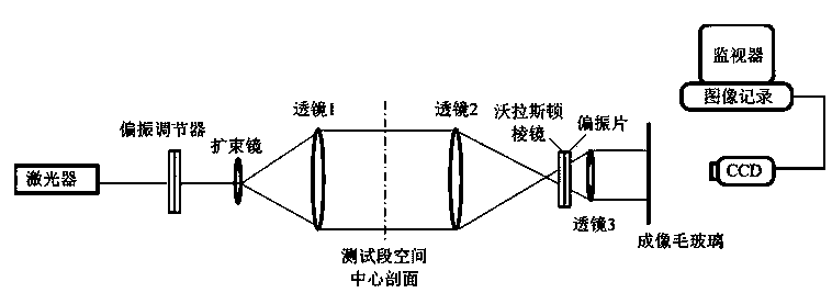
[0045] figure 1 A schematic diagram showing the differential interference fringe pattern with carrier fringes collected at any time before and during the airflow injection by using a Wollaston prism differential interferometer. The linearly polarized light emitted by the laser is adjusted to the direction of 45° with the optical axis of the Wollaston prism by the polarization direction adjuster; the beam expander and the collimator lens 1 convert the laser beam into a beam-expanded parallel light, and pass through Flow field; lens 2 and lens 3 narrow the field of view of the beam, and image the central section of the flow field on the frosted glass.

[0046] The Wollaston prism is placed near the rear focal point of the lens 2, and the incident light is divided into two beams of linearly polarized light separated from each other and whose vibration directions are perpendicular to each other. By adjusting the distance between the center of the Wollaston prism and the rear foca...


PUM


Abstract

The invention discloses a measurement method of a gas injection flow field. A differential interferometry system is formed by Wollaston prism optical elements; the center section of a spatial flow field of a test section is imaged, and differential interference fringe charts with carrier wave fringes are collected at any moment before air flow injection and during air flow injection, so that the fringe order distribution and the fluid optical refractive index gradient in a whole field are obtained, and the density gradient field, the density field, the temperature field and the temperature gradient field of a fluid also can be obtained synchronously. The analyzing and treating method of fringe charts, which is disclosed by the invention, can be used for basically eliminating experiment errors caused by the differential interferometry system, has a low shock-resistant requirement, is convenient to apply, and overcomes problems caused by flow field instability.

Description

technical field [0001] The invention relates to a method for measuring a gas jet flow field. Background technique [0002] The measurement of the jet flow field has very important applications in the process industry, aviation and other related fields. Compared with the point-by-point and contact detection technology, the optical flow display technology has many advantages: 1) It can give the full Field information, not only has a large information capacity, but also has an intuitive information display; 2) The light travels very quickly and can be used for dynamic measurement of the flow field; 3) There is no mechanical probe, so there is no interference with the flow field to be measured. [0003] Optical interference techniques such as classical interferometry and electronic speckle interferometry measure the change of optical path difference, and then measure the refractive index of the fluid, so as to obtain the spatial distribution of fluid density or temperature. How...

Claims


Application Information

Patent Timeline
Patent Type & Authority Applications(China)
IPC IPC(8): G01N21/45
Inventor 韩九林
Owner ZHEJIANG UNIV
Why Eureka
Try Eureka