Method used for improving stability of doped MgO dielectric protective layer and plasma display screen
A technology for plasma display and media protection, which is used in alternating current plasma display panels, ion implantation plating, coating, etc. Effect
- Summary
- Abstract
- Description
- Claims
- Application Information
AI Technical Summary
Problems solved by technology
Method used
Image
Examples
Embodiment 1
[0029] 1) A CaO-doped MgO target is used as an evaporation source, and a doped MgO dielectric protective layer is evaporated on the front substrate on which electrodes and dielectric layers have been fabricated, with a thickness of 700 nm.
[0030] 2) Put the vapor-deposited front substrate into a sintering furnace for heat treatment, the sintering atmosphere is air, the heating source is infrared heating, the heating temperature is 300° C., and the heating time is 10 minutes.
[0031] 3) After the heat treatment, align the front substrate and the rear substrate.
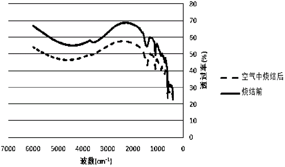
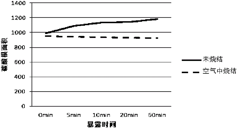
[0032] Analyze below in conjunction with the sample of embodiment 1: figure 1 Shown are the Fourier transform infrared spectrograms of the heat-treated sample and the non-heat-treated sample in air; figure 2 Shown is the comparison chart of the carbonate absorption peak area of the sample after heat treatment in air and the sample without heat treatment after exposure in air for different time. Comparing the two,...
Embodiment 2
[0034] 1) The MgO target doped with SrO is used as the evaporation source, and the dielectric protection is evaporated on the front substrate on which the electrode and the dielectric layer have been fabricated, with a thickness of 900nm.
[0035] 2) After evaporation, put the front substrate into a sintering furnace for heat treatment, the sintering atmosphere is nitrogen, the heating source is infrared heating, the heating temperature is 600°C, and the heating time is 60 minutes.
[0036] 3) After the heat treatment, align the front substrate and the rear substrate.
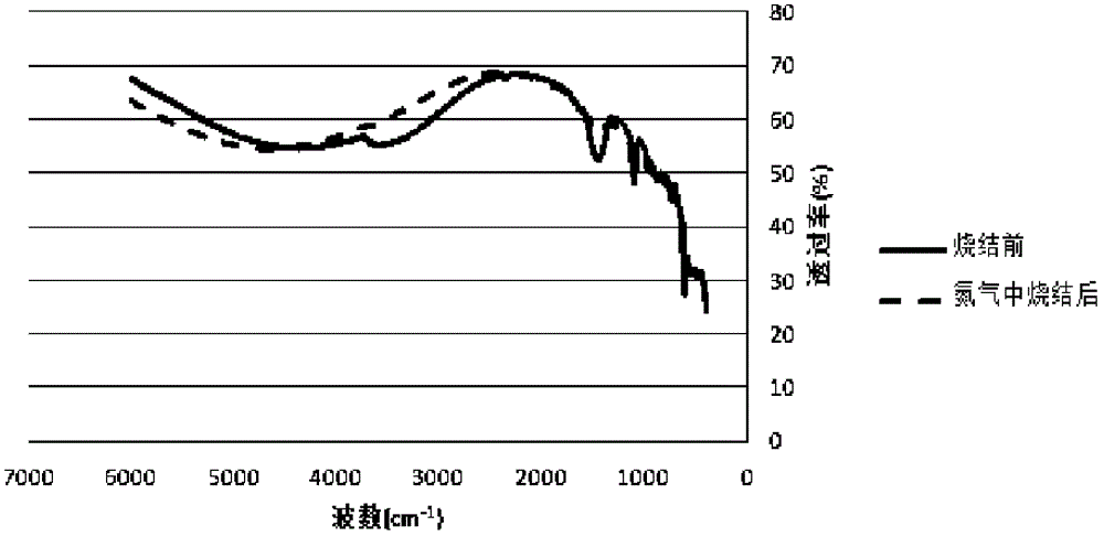
[0037] Analyze below in conjunction with the sample of embodiment 2: image 3 Shown are the Fourier transform infrared spectra of the sample after heat treatment in nitrogen and the sample without heat treatment; Figure 4 Shown is a comparison chart of the carbonate absorption peak area of the sample after heat treatment in nitrogen and the sample without heat treatment exposed in air for different times. ...
PUM
| Property | Measurement | Unit |
|---|---|---|
| Absorption peak | aaaaa | aaaaa |
Abstract
Description
Claims
Application Information
 - R&D
- Intellectual Property
- Life Sciences
- Materials
- Tech Scout
- Unparalleled Data Quality
- Higher Quality Content
- 60% Fewer Hallucinations
Browse by: Latest US Patents, China's latest patents, Technical Efficacy Thesaurus, Application Domain, Technology Topic, Popular Technical Reports.
© 2025 PatSnap. All rights reserved.Legal|Privacy policy|Modern Slavery Act Transparency Statement|Sitemap|About US| Contact US: help@patsnap.com


