
Control method of excited push-pull converter with zero-voltage switching and excited push-pull converter

A technology of zero-voltage switching and control method, which is applied in the control of other excited push-pull converters, and in the field of other excited push-pull converters, which can solve the problem of large switching loss, reduced duty cycle of driving signals, and inability to achieve zero voltage switch and other issues, to achieve the effect of reduced volume, high conversion efficiency, and reduced total cost

Active Publication Date: 2014-07-23
MORNSUN GUANGZHOU SCI & TECH
View PDF6 Cites 16 Cited by
  • Summary
  • Abstract
  • Description
  • Claims
  • Application Information

AI Technical Summary

Problems solved by technology

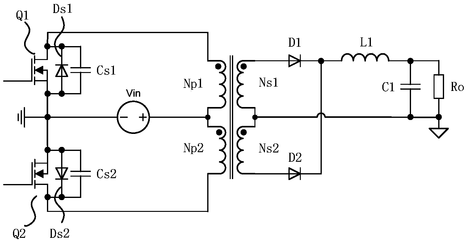
The control method of this scheme is: when the input voltage is low or the output is heavy load, the push-pull converter needs to work under the condition that the duty cycle of the driving signal is close to 0.5; and when the input voltage is high or the output is light Under the condition of load, the push-pull converter works in PWM mode. At this time, the duty cycle of the driving signal controlling the two switching tubes on the primary side is significantly reduced. In this working mode, the circuit cannot realize zero-voltage switching.
The disadvantage of this implementation scheme is that the conditions for the circuit to realize zero-voltage switching are always related to the size of the output load, and under the condition of high input voltage or light output load, this control method will not be able to achieve zero-voltage switching, especially at high Under the condition of high frequency, it will bring a large switching loss

Method used


Image

  • Control method of excited push-pull converter with zero-voltage switching and excited push-pull converter
  • Control method of excited push-pull converter with zero-voltage switching and excited push-pull converter
  • Control method of excited push-pull converter with zero-voltage switching and excited push-pull converter

Examples


Embodiment Construction

[0040] Figure 4 It is the schematic diagram of the circuit of the first embodiment of the present invention. As shown in the figure, this circuit includes an input voltage source Vin, whose positive pole is connected to the center tap of the primary winding of the transformer T1, and whose negative pole is connected to the ground; Connected first main power MOS transistor Q11 and second main power MOS transistor Q12, the drain of the first main power MOS transistor Q11 is connected to one end of the first primary winding of the transformer, and the source is connected to ground; the second main power MOS transistor Q11 The drain of the tube Q12 is connected to one end of the second primary winding of the transformer, and the source is connected to the ground; the gates of Q11 and Q12 are respectively connected to the drive signal output ports of the controller. The secondary side of the coupling transformer T1 is connected to the full-wave rectification filter circuit, the fu...


PUM


Abstract

The invention discloses a control method of an excited push-pull converter with zero-voltage switching and the excited push-pull converter. According to the magnitude of exciting current of a coupling transformer in the excited push-pull converter, the dead time of two main power MOS tube driving signals output by a controller is adjusted, in the dead time, the energy of the exciting current of the coupling transformer is used for completely releasing charges stored in a parasitic capacitor of one main power MOS tube, needing to be switched from the switch-off state to the switch-on state, in the excited push-pull converter, when diodes which are arranged in the main power MOS tube and are connected in an anti-parallel mode are switched on, the controller outputs a driving signal to control the main power MOS tube to be switched on, and zero-voltage switching is realized. The conditions for realizing zero-voltage switching of the primary MOS tube are irrelevant to the range of an input voltage and an output load, and it can be ensured that zero-voltage switching of a circuit is realized within the full-load range.

Description

technical field [0001] The invention relates to a push-pull converter, in particular to an excited push-pull converter with zero-voltage switching characteristics, and also to a control method for the excited push-pull converter with zero-voltage switching. Background technique [0002] The circuit structure of the push-pull converter is simple, the drive circuit does not need to be isolated, the transformer is bidirectionally excited when the circuit is working, and the utilization rate of the magnetic core is high. Therefore, this kind of converter has the advantages of small size, high efficiency and good dynamic response, but because the converter When working, the voltage stress of the switch tube is twice the input voltage, so this kind of converter is often used in medium and high power occasions with low voltage input. [0003] The push-pull converter circuit topology is as figure 1 As shown, the two switching tubes Q1 and Q2 in the circuit are respectively connecte...

Claims


Application Information

Patent Timeline
IPC IPC(8): H02M3/337
CPCY02B70/10
Inventor 周耀彬余凤兵杨正兰
Owner MORNSUN GUANGZHOU SCI & TECH
Learn More