Power amplifier

A power amplifier and transistor technology, applied in power amplifiers, improving amplifiers to reduce nonlinear distortion, and improving amplifiers to reduce temperature/power supply voltage changes, etc., can solve problems such as reducing output power and power output linearity deterioration.

Inactive Publication Date: 2014-07-23
HANGZHOU SILAN MICROELECTRONICS
View PDF7 Cites 7 Cited by
  • Summary
  • Abstract
  • Description
  • Claims
  • Application Information

AI Technical Summary

Problems solved by technology

As a result, the output power may be reduced and the linearity of the power output may be degraded

Method used


Image

  • Power amplifier
  • Power amplifier
  • Power amplifier

Examples


Embodiment Construction

[0021] Various embodiments of the invention will be described in more detail below with reference to the accompanying drawings. In the various drawings, the same elements are denoted by the same or similar reference numerals. For the sake of clarity, various parts in the drawings have not been drawn to scale.

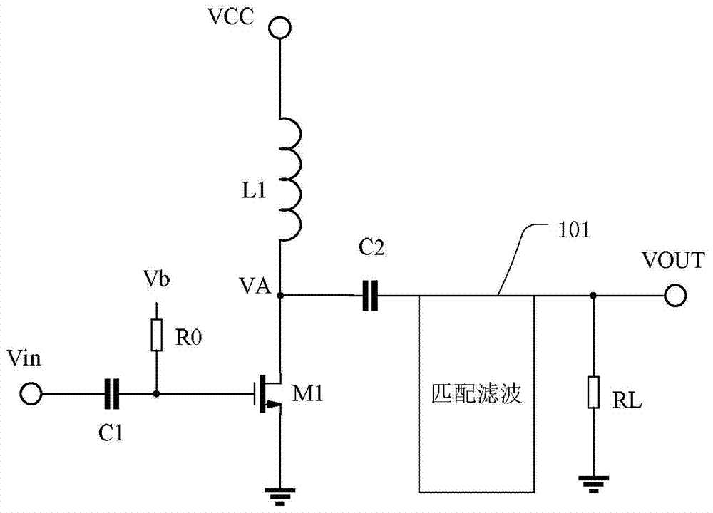
[0022] figure 1 is a schematic circuit diagram of a power amplifier according to the prior art. The power amplifier includes a first transistor M1 and a choke inductor L1 connected in series, an input coupling circuit electrically connected to the gate of the first transistor M1, and an output connected to an intermediate node of the first transistor M1 and the choke inductor L1 coupling circuit.

[0023] The input coupling circuit comprises, for example, a first capacitor C1 connected between the input terminal of the power amplifier and the gate of the first transistor M1. The gate of the first transistor M1 is also connected to the bias resistor R0. The bias vol...


PUM


Abstract

The invention discloses a power amplifier which comprises a first resistor, a choke inductor, a first transistor, an input coupling circuit and an output coupling circuit. The first resistor, the choke inductor and the first transistor are connected between the power source end and the ground in series. The input coupling circuit is connected between the input end of the power amplifier and the grid electrode of the first transistor. The output coupling circuit is connected among the output end of the power amplifier, the chock inductor and a first middle node of the first transistor. The power amplifier further comprises a biasing circuit connected with the grid electrode of the first transistor, so that a working point of the first transistor changes along with the change of the supply voltage. According to the power amplifier, the voltage resistant requirement of the first transistor can be lowered, the direct current component of an output signal of the first middle node of the first transistor is approximately equal to a half of the supply voltage so as to ensure the output power of the power amplifier, and reliability and linearity can be improved.

Description

technical field [0001] This invention relates to electronic circuits and in particular to power amplifiers. Background technique [0002] Power amplifiers are commonly used as audio amplifiers and radio frequency amplifiers to generate a power output to drive a load. In radio frequency applications, the power amplifier is a necessary module to amplify the signal before transmitting it, and then the amplified signal can be coupled to the antenna. [0003] According to the working mode of the power amplifier, the power amplifier can be divided into Class A, Class B, Class AB, Class C, Class D, Class E, etc. Different types of power amplifiers have different output voltage waveforms. The amplitude of the output waveform of the power amplifier may reach 2 to 4 times the power supply voltage, thus requiring that the withstand voltage of the power transistor in the power amplifier should also be 2 to 4 times the power supply voltage. [0004] For some consumer electronics, the ...

Claims


Application Information

Patent Timeline
IPC IPC(8): H03F3/20H03F1/30H03F1/32
Inventor 郑烷胡铁刚
Owner HANGZHOU SILAN MICROELECTRONICS
Why Eureka
Try Eureka