A Sampling Clock Generation Circuit for Multi-channel Time-Interleaved Analog-to-Digital Converter

A technology for analog-to-digital converters and generating circuits, applied in the direction of analog/digital conversion calibration/testing, etc., can solve problems such as increasing multi-channel sampling clock errors, affecting phase calibration accuracy, reducing conversion accuracy, etc., to reduce the cost of hardware , Eliminate errors, improve the effect of accuracy

Active Publication Date: 2017-06-13
BEIJING MXTRONICS CORP +1
View PDF3 Cites 0 Cited by
  • Summary
  • Abstract
  • Description
  • Claims
  • Application Information

AI Technical Summary

Problems solved by technology

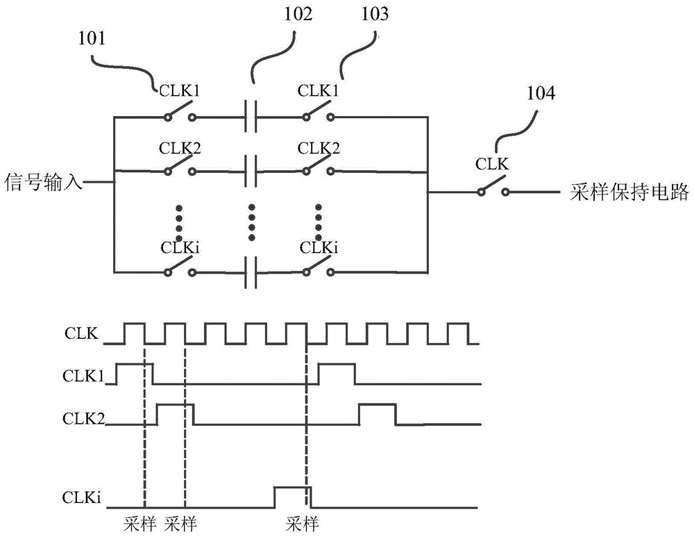
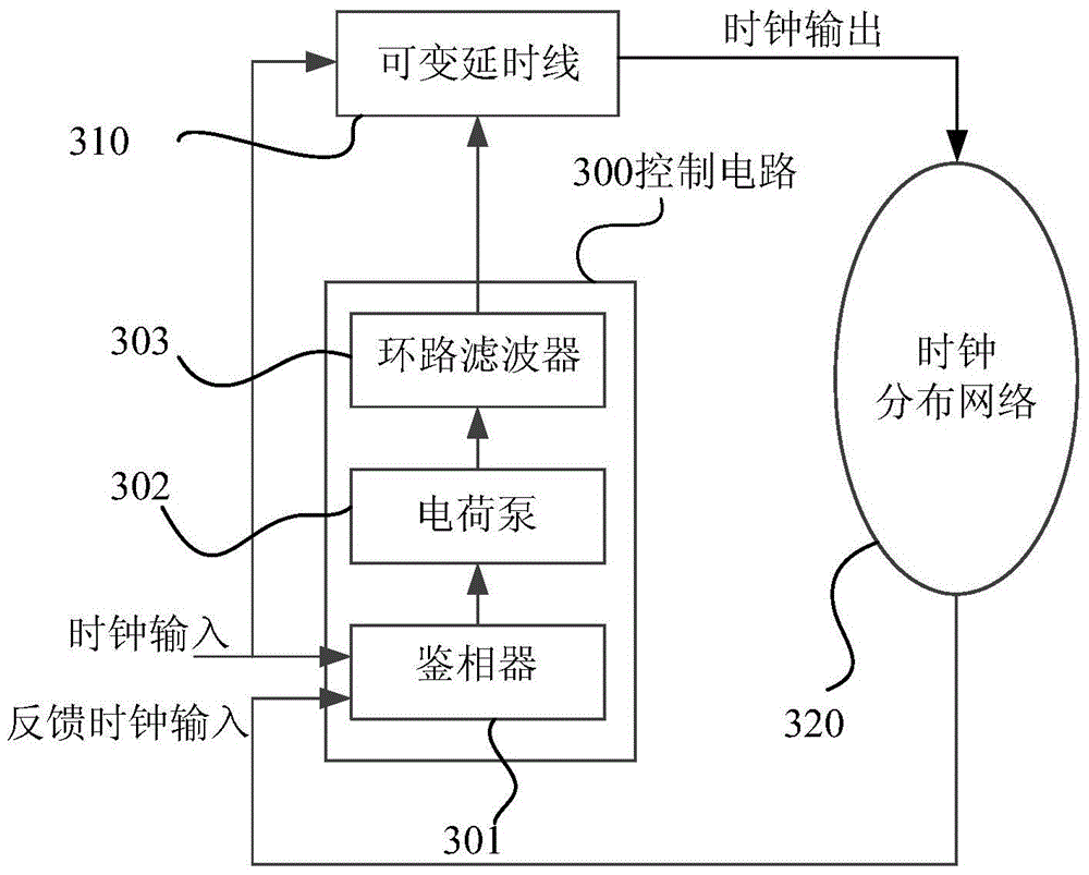
The delay-locked loop can set the number of delay units inside the controllable delay line 304 to obtain clock signals of equal phases with different phase difference accuracy, but the delay-locked loop requires the phase difference between the input clock signal and the feedback clock signal in order to achieve locking. is zero, that is to say, the feedback clock signal is obtained by delaying the input clock signal by an integer number of clock cycles, which increases the difficulty of the design of the entire loop. In order to ensure high phase alignment accuracy, the number of delay units will be large. If it is realized by digital method, it is difficult to ensure its high-frequency operation. If it is realized by analog method, it is necessary to ensure that the delay unit has good noise suppression ability. Any noise coupled from power supply and substrate will affect its operation when the converter is working. The accuracy of the phase alignment, and the mismatch of the clock distribution path of each multi-channel sampling clock in the clock distribution network 305 will further increase the error of the multi-channel sampling clock
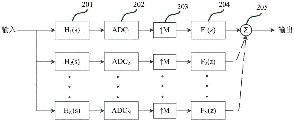
[0009] In a multi-channel time-interleaved high-speed high-precision analog-to-digital converter, the gain error, offset error and sampling clock error between channels will affect the static and dynamic performance of the converter, reduce the conversion accuracy, and need to be calibrated for errors. The sampling clock error has become the bottleneck in the design of ultra-high-speed data converters. It is difficult to obtain good results by statistically extracting the sampling clock error between channels and compensating the output data of the converter. Therefore, how to better obtain multi-channel sampling clock It has become a trend in current circuit design

Method used


Image

  • A Sampling Clock Generation Circuit for Multi-channel Time-Interleaved Analog-to-Digital Converter
  • A Sampling Clock Generation Circuit for Multi-channel Time-Interleaved Analog-to-Digital Converter
  • A Sampling Clock Generation Circuit for Multi-channel Time-Interleaved Analog-to-Digital Converter

Examples


Embodiment Construction

[0040] Below in conjunction with accompanying drawing and specific embodiment the present invention is described in further detail:

[0041] Such as Figure 4 Shown is a schematic structural diagram of the sampling clock generation circuit of the present invention. It can be seen from the figure that the sampling clock generation circuit of the present invention is composed of a multi-phase clock generation module 400 , a duty cycle recovery circuit 410 , and a channel selection module 420 . The multi-phase clock generating module 400 generates multi-phase clock signals required by the multi-channel digital-to-analog converter, and at the same time compensates phase errors of the multi-phase clock signals to ensure the accuracy of sampling clocks between channels of the digital-to-analog converter. The duty cycle recovery circuit 410 is used to perform edge synchronization operation on the multi-phase clock generated by the multi-phase clock generation module and the input glo...


PUM


Abstract

The invention relates to a sampling clock generating circuit for a multi-channel time-interleaved analog-to-digital converter, which is composed of a multi-phase clock generating module, a duty cycle recovery circuit and a channel selection module, wherein the multi-phase clock generating module generates a multi-channel digital-analog The multi-phase clock signal required by the converter, and at the same time compensate the phase error of the multi-phase clock signal to ensure the accuracy of the sampling clock between the channels of the analog-to-digital converter; The phase clock performs an edge adjustment operation, that is, restores the duty ratio, and the output multi-phase clock signal is used as the sampling clock signal of the sample and hold circuit; the channel selection module receives the control code written by the external serial port, judges the number of internal channels required, and controls The internal channel is turned on and off, and at the same time, the internal multi-phase clock of the multi-phase pulse module is selected according to the control code, so as to realize the generation of down-sampling clocks selected by different channels.

Description

technical field [0001] The invention relates to a sampling clock generating circuit for a multi-channel time-interleaved analog-to-digital converter, which belongs to the field of integrated circuit mixed signal design and is mainly used in a multi-channel time-interleaved converter to reduce the error of the sampling clock and improve the performance of the converter . Background technique [0002] In 1980, Black and Hodges proposed multi-channel time-interleaved ADC technology for the first time. This technology uses multiple low-sampling-rate sub-ADCs to work in parallel, and samples the same input signal through sampling clock interleaving to increase the sampling rate. This technology realizes the same sampling The requirements of each sub-ADC are reduced under the condition of low rate, which makes it more and more used in high-speed and high-precision converters. [0003] Although the multi-channel time-interleaved analog-to-digital converter can increase the samplin...

Claims


Application Information

Patent Timeline
Patent Type & Authority Patents(China)
IPC IPC(8): H03M1/10
Inventor 何斌王宗民张铁良杨松蔡伟李琦嶂李国峰虞坚李浩
Owner BEIJING MXTRONICS CORP
Why Eureka
Try Eureka