
Steel-smelting furnace and smelting process

A steel-making furnace and process technology, applied in the field of iron and steel metallurgy, can solve the problems of prolonging the smelting cycle, prolonging the smelting rhythm, and long smelting cycle, and achieving the effects of improving the metal yield, reducing the consumption of deoxidizers, and shortening the smelting time.

Inactive Publication Date: 2014-07-30
MCC CAPITAL ENGINEERING & RESEARCH
View PDF3 Cites 2 Cited by
  • Summary
  • Abstract
  • Description
  • Claims
  • Application Information

AI Technical Summary

Problems solved by technology

However, in the process of converter steelmaking, since the tapping hole is located on the upper part of the cylindrical furnace body, the slag needs to be poured out from the furnace port after the smelting is completed. The inclination increases energy consumption and prolongs the smelting rhythm
When the converter adopts low-slag smelting process to smelt low-phosphorus steel, the oxygen lance needs to be lifted above the furnace mouth at the end of the dephosphorization period, and part of the slag is poured out by turning the furnace back, which prolongs the smelting cycle. At this time, due to the serious foaming of the dephosphorization slag, the This increases the difficulty of slag dumping, and the poured out high phosphorus slag contains a lot of iron loss, which increases the consumption of steel materials
[0003] Traditional electric furnace steelmaking has high power consumption and production costs, and long smelting cycle. In order to reduce energy consumption and production costs, a large amount of molten iron is added to electric furnace steelmaking. The proportion of molten iron in some electric furnaces has reached or exceeded 70%, basically realizing the conversion of electric furnaces However, due to the small free space of the electric furnace body itself, the low oxygen supply intensity and the difficulty of slagging, the molten pool in the furnace has a slow flow rate and poor uniformity of molten pool composition and temperature, resulting in slow reaction rate and short blowing time. Long length, severe spattering, low metal yield and high production cost seriously hinder the development and promotion of electric furnace steelmaking

Method used


Image

  • Steel-smelting furnace and smelting process
  • Steel-smelting furnace and smelting process
  • Steel-smelting furnace and smelting process

Examples


Embodiment Construction

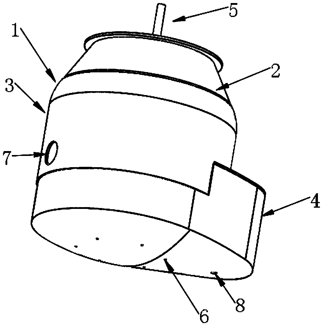
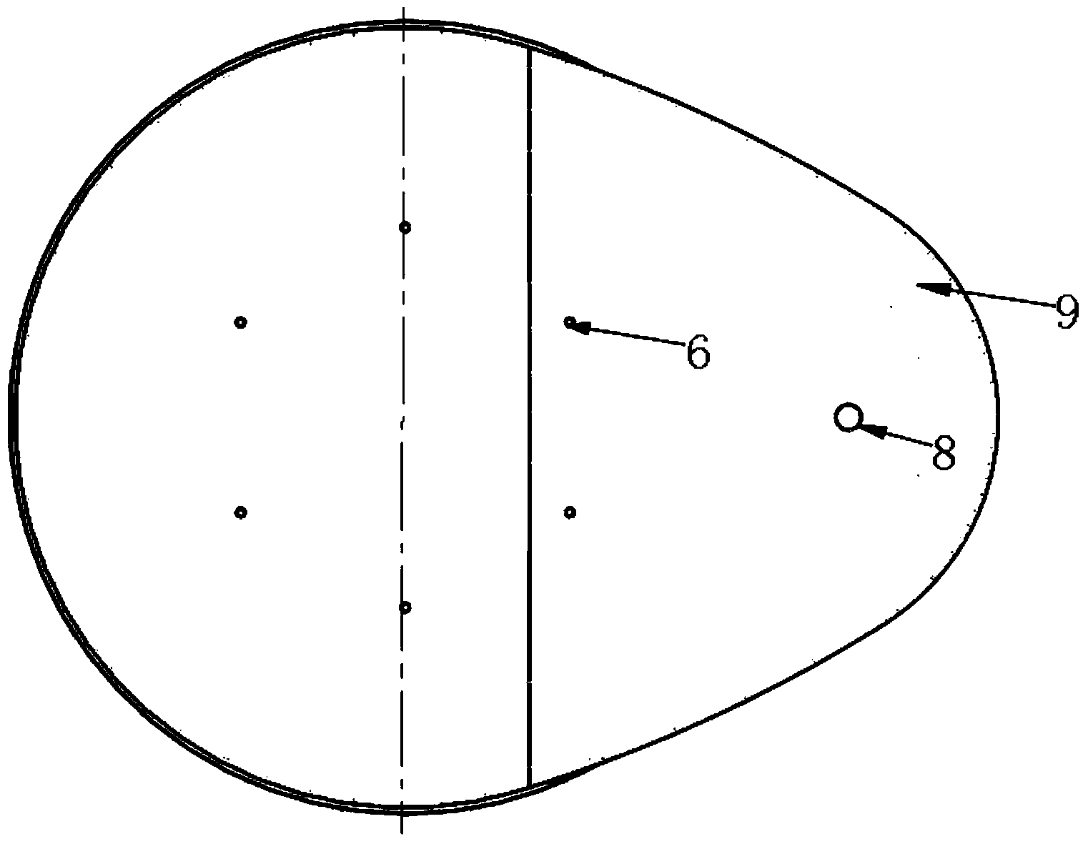
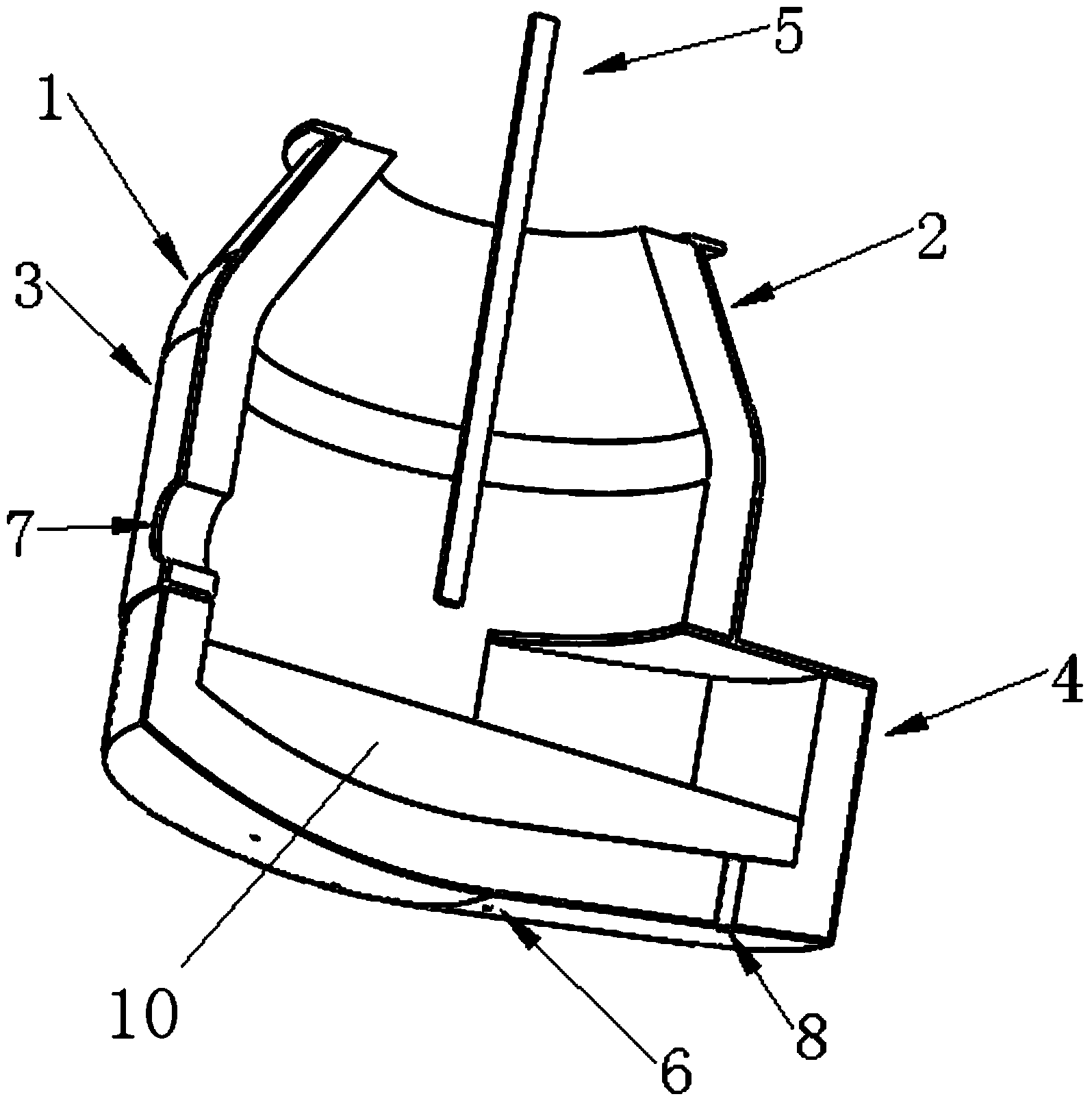
[0028] The steelmaking furnace of the present invention will be described in further detail below in conjunction with the accompanying drawings. A steelmaking furnace, comprising a shaft 3 and an eccentric furnace bottom 4, the furnace shaft 3 is cylindrical, the furnace shaft 3 is provided with a slag outlet 7, and the projection of the center of gravity of the cross section of the eccentric furnace bottom 4 in the vertical direction deviates from the furnace The projection of the center of gravity of the body 3 cross-sections in the vertical direction, such as the projection of the center of gravity of the 4 cross-sections of the eccentric furnace bottom in the vertical direction is figure 2 The center of gravity of the shown cam shape, the projection of the center of gravity of the furnace shaft 3 cross-section in the vertical direction is figure 2 The center of the circle on the left side of the middle cam shape, that is, figure 2 The projection of the center of gravit...


PUM


Abstract

The invention provides a steel-smelting furnace and a smelting process. The steel-smelting furnace comprises a furnace body (3) and an eccentric furnace bottom (4), wherein a slag hole (7) is formed in the furnace body (3); the projection of the center of gravity of the cross section of the eccentric furnace bottom (4) in the vertical direction deviates from the projection of the center of gravity of the cross section of the furnace body (3) in the vertical direction; the cross-sectional area of the eccentric furnace bottom (4) is larger than that of the furnace body (3); a steel outlet (8) is formed in the bottom of the eccentric furnace bottom (4). The smelting process can adopt a one-time slagging process or a two-time slagging process, and can be used for shortening the smelting time by 2-5 minutes, improving the steel smelting efficiency, realizing less slag smelting, reducing the consumption of a slagging material, reducing the consumption of a deoxidizer, improving the metal yield, and avoiding furnace slag carried out by a conventional steel-smelting furnace in steel tapping from polluting a molten steel, thereby meeting the technical requirements of efficient steel smelting.

Description

technical field [0001] The invention relates to the technical field of iron and steel metallurgy, in particular to a steelmaking furnace and a smelting process using the steelmaking furnace. Background technique [0002] Converter steelmaking and electric furnace steelmaking are currently the two most important steelmaking methods in the world, of which the proportion of converter steel accounts for more than 60%, and the proportion of electric furnace steel accounts for about 30%. The steelmaking process adopts enhanced oxygen supply technology and bottom blowing gas strong stirring technology, which makes the rhythm of blowing continuously accelerated and has achieved good metallurgical effect. However, in the converter steelmaking process, since the tapping hole is located on the upper part of the cylindrical furnace body, the slag needs to be poured out from the furnace port after the smelting is completed. The inclination increases energy consumption and prolongs the s...

Claims


Application Information

Patent Timeline
Patent Type & Authority Applications(China)
IPC IPC(8): C21C5/56
CPCY02P10/20
Inventor 潘宏涛戴年建张温永李强邱明罡戈义彬吕明
Owner MCC CAPITAL ENGINEERING & RESEARCH
Learn More