Hydraulic oil treatment device for hydraulic equipment

A processing device and hydraulic equipment technology, applied in the hydraulic field, can solve problems such as easy blockage of radiator pipes, easily damaged oil leakage, and increased oil return resistance, so as to reduce equipment operating costs, reduce installed capacity, and save energy.

Inactive Publication Date: 2014-07-30
贾瑞勇
View PDF0 Cites 2 Cited by
  • Summary
  • Abstract
  • Description
  • Claims
  • Application Information

AI Technical Summary

Problems solved by technology

[0009] At present, the hydraulic oil storage and cooling of hydraulic equipment is simply assembled by hydraulic oil tank and hydraulic cooler through pipelines. The problems caused by this combination are: increased oil return resistance, easy blockage of radiator pipes, and easy work under hydraulic impact Damaged and leaked oil; scale is easily generated inside the cooler, and oil and water leaks are easy to pollute the oil; large investment, high energy consumption, complex structure, and high failure rate

Method used


Image

  • Hydraulic oil treatment device for hydraulic equipment
  • Hydraulic oil treatment device for hydraulic equipment
  • Hydraulic oil treatment device for hydraulic equipment

Examples


Embodiment Construction

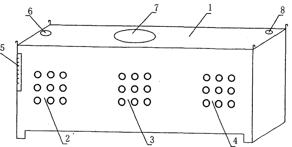
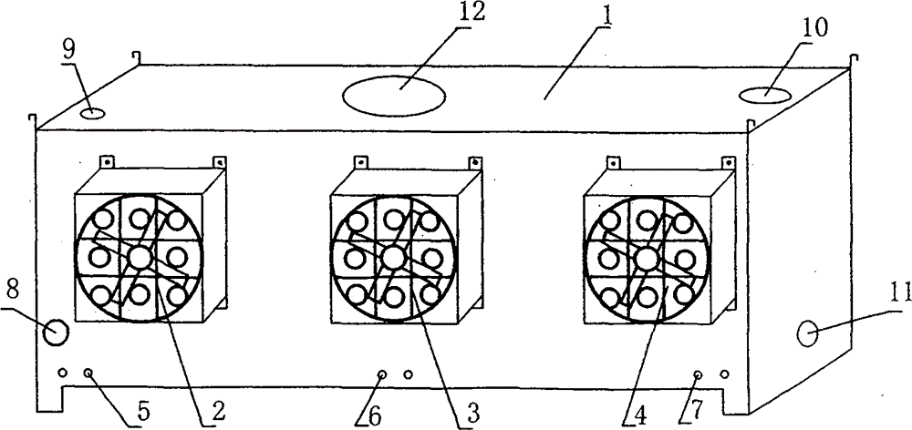
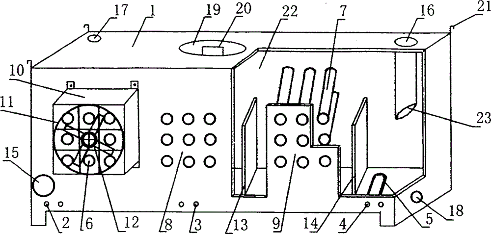
[0034] The hydraulic oil treatment device of the hydraulic system of the 200-ton CNC hydraulic press and the Figure 4 , Figure 5 , Figure 6 The present invention is further described.

[0035] 1. Calculate the total amount of oil in the hydraulic system

[0036] The cylinder of this hydraulic machine has a diameter of 360mm, a stroke of 500mm, a 22KW-6 motor, and a 190L Rexroth constant power electronically controlled proportional variable pump.

[0037] 2. Determine the cabinet parameters

[0038] According to the condition of the main engine, the parameters of the box are determined to be 1400mm in length, 660mm in width, and 740mm in height. The total volume is about 680L, the effective volume is about 540L, and 500L of oil can be filled.

[0039] 3. Purchasing materials and accessories.

[0040]The thickness of the box plate is 5mm, 2 pieces in total of 660 in width and 1400 in length, 2 pieces in total of 740 in width and 1400 in length, and 2 pieces in total of 6...


PUM


Abstract

The invention relates to a hydraulic oil treatment device for hydraulic equipment, and belongs to the hydraulic technical field. The hydraulic oil treatment device consists of a metal box body and accessories thereof, a heater, cooling pipe groups, an axial flow fan, an air flow guide cover and a safety protection net, wherein the box body is formed by welding iron plates or stainless steel plates; cooling pipes are arranged at corresponding positions on two non-adjacent box walls of the box body; two ends of the cooling pipes are welded together with the walls of the box body; multiple cooling pipes form a cooling pipe group; the axial flow fan is arranged at an air inlet in one side of each cooling pipe group; a bracket of the axial flow fan is fixed on the box body through screws; the air flow guide cover is arranged on the outer side of the axial flow fan; the safety protection net is arranged outside the air flow guide cover. The hydraulic oil treatment device has the advantages of energy conservation, environment friendliness, compact structure, complete functions, good oil liquid temperature control effect and safety and stability in running, and can be widely applied to hydraulic equipment industries and equipment for treating oil liquid temperature.

Description

technical field [0001] The invention relates to a hydraulic oil treatment device for hydraulic equipment, which belongs to the technical field of hydraulic pressure. Background technique [0002] At present, the hydraulic oil tank and hydraulic oil cooler used in hydraulic equipment are two hydraulic accessories with completely different functions. The manufacturer of the hydraulic oil tank designs, processes and manufactures the hydraulic oil tank; the design, processing and manufacture of the hydraulic oil cooler is completed by the manufacturer of the hydraulic oil cooler; the two manufacturers optimize the structure and performance. [0003] The main function of the hydraulic oil tank is to store oil, dissipate heat, release gas in the oil, and precipitate impurities in the oil. The function of the hydraulic oil cooler is to reduce the oil temperature to the working temperature through efficient heat exchange to ensure the normal operation of the main engine. [0004]...

Claims


Application Information

Patent Timeline
Patent Type & Authority Applications(China)
IPC IPC(8): F15B21/04
Inventor 贾瑞勇
Owner 贾瑞勇
Why Eureka
Try Eureka