Quantum dot, method for manufacturing quantum dot and quantum dot LED device

A technology of LED devices and quantum dots, applied in electrical components, nanotechnology, circuits, etc., can solve the problems of reducing the optical performance and structural defects of quantum dots with core-shell structure, and achieve high electroluminescence efficiency, high spectral purity, and high light Effect of Luminescent Quantum Yield

Inactive Publication Date: 2014-07-30
ZHENGZHOU UNIV
View PDF4 Cites 11 Cited by
  • Summary
  • Abstract
  • Description
  • Claims
  • Application Information

AI Technical Summary

Problems solved by technology

[0004] But from a crystallographic point of view, ZnS is not an ideal shell material. This is because the lattice mismatch between CdSe and ZnS is 12%, and the thermal expansion coefficient differs by 30%. Such a large lattice mismatch The coordination prevents the epitaxial growth of the ZnS shell. As the shell grows thicker, the stress continues to increase. When the quantum dots are cooled from their growth temperature, the stress release of the shell will form structural defects at the core-shell interface. These defects will Reducing the Optical Properties of Core-Shell Structured Quantum Dots

Method used


Image

  • Quantum dot, method for manufacturing quantum dot and quantum dot LED device
  • Quantum dot, method for manufacturing quantum dot and quantum dot LED device
  • Quantum dot, method for manufacturing quantum dot and quantum dot LED device

Examples


Embodiment 1

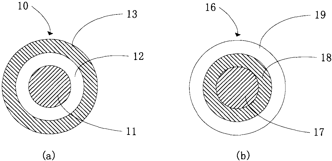
[0049] figure 2 Shown is a schematic diagram of the structure of the quantum dots in this embodiment. like figure 2 As shown in (a), the quantum dot 10 in this embodiment includes: a CdSe core 11, the CdSe core 11 is covered with a first shell 12, and the first shell 12 is covered with a second shell 13 , the first shell layer 12 is an exciton confinement layer, and the second shell layer 13 is a stress compensation layer. Wherein, the stress compensation layer 13 is a ZnCdS layer, and the exciton confinement layer 12 is a ZnS layer.

[0050] like figure 2 Shown in (b), the comparative example quantum dot 16 in the present embodiment comprises: CdSe core 17, and CdSe core 17 is covered with shell layer, and described shell layer is by inside and outside including: ZnS layer 18 and ZnCdS layer 19.

[0051] Image 6 It is the X-ray diffraction pattern of the quantum dot crystal structure in this embodiment. The crystal structure of quantum dots was measured by Bruker D...

Embodiment 2

[0061] Figure 5 It is a flowchart of the quantum dot preparation method in the embodiment of the present invention. as the picture shows:

[0062] Step S1: making CdSe core 11 with Cd precursor and Se precursor, and the CdSe core 11 is formed in the first solution.

[0063] Specifically, the stearylamine-coated quantum dot CdSe core 11 is prepared by using a general hot injection method from CdO and Se as precursors. The CdSe nuclear quantum dot has a first exciton absorption peak of 528nm, which is precipitated by adding methanol, separated and then Centrifuge to remove by-products and unreacted precursors. Quantum dot CdSe cores are dispersed in hexane to form a first solution for further synthesis.

[0064] Step S2: growing a first shell 12 outside the CdSe core 11, and the first shell 11 is formed in the second solution.

[0065] Specifically, CdSe / ZnS and CdSe / ZnS were synthesized by the successive ion layer adsorption and reaction (Successiveion Layer Adsorption and...

Embodiment 3

[0069] Figure 4 It is a schematic diagram of the structure of QD-LED in this embodiment (please supplement the accompanying drawings). As shown, the LEDs in this embodiment include:

[0070] Substrate 41, such as glass 43 with ITO film layer 42, ITO is used as anode;

[0071] The hole injection layer 44 on the substrate is, for example, PEDOT:PSS with a thickness of 40 nm;

[0072] The hole transport layer 45 above the hole injection layer 44 is, for example, poly-TPD with a thickness of 40 nm;

[0073] The quantum dot luminescent layer 46 on the 45 of the hole transport layer, the quantum dot luminescent layer 46 includes: a CdSe core, a first shell layer covering the CdSe core, and a second shell layer covering the first shell layer , wherein, the first shell layer is an exciton confinement layer, and the second shell layer is a stress compensation layer; in this embodiment, preferably, the stress compensation layer of the quantum dots is a ZnCdS layer, and the quantum d...


PUM


Abstract

The invention provides a quantum dot. The quantum dot comprises a CdSe core, a first shell layer and a second shell layer, wherein the CdSe core is covered with the first shell layer, the first shell layer is covered with the second shell layer, the first shell layer serves as an excition limiting layer, the second shell layer serves as a stress compensation layer, the first shell layer is a ZnS layer, and the second shell layer is a ZnCdS layer. Due to the design of the external shell layers of the CdSe colloid quantum dot, the CdSe/ZnS/ZnCdS colloid quantum dot with the stress compensation function is synthetised. Compared with a traditional CdSe/ZnCdS/ZnS quantum dot, the quantum dot has the advantages that the photoluminescence quantum yield is higher, the photoluminescence efficiency of a semiconductor light emitting diode made of the quantum dot is higher, the spectral purity is higher under the high injection current condition, and thus the quantum dot is more suitable for manufacturing of a high-definition display screen.

Description

technical field [0001] The invention relates to the technical field of electronic devices, in particular to a quantum dot LED device. Background technique [0002] Colloidal nanoscale quantum dots (Quantum Dots, QDs) have recently become a hot area of ​​fundamental research in nanoscience, and have also received extensive attention in optoelectronic device technologies such as LEDs, photodetectors, and solar cells. Nano-quantum dots have many advantages such as wide chromatographic tunability, excellent color purity, high luminous efficiency, and low preparation cost, so they have broad application prospects in next-generation color displays. [0003] In recent years, CdSe / ZnS core-shell quantum dots have gradually become a research hotspot. ZnS has a large band gap and can form an I-type heterojunction with the CdSe core, thereby achieving an effective electronic passivation effect on the CdSe core. like figure 1 As shown, the core-shell quantum dots consist of a CdSe cor...

Claims


Application Information

Patent Timeline
Patent Type & Authority Applications(China)
IPC IPC(8): H01L33/50H01L33/00B82Y20/00B82Y40/00
CPCH01L33/06B82Y30/00B82Y40/00H01L33/0083H01L33/28
Inventor 张懿强
Owner ZHENGZHOU UNIV
Why Eureka
Try Eureka