Microstrip antenna with phase shifting function

A technology of microstrip antenna and function, applied in the direction of antenna, resonant antenna, electrical components, etc., can solve the problem of not considering the phase tuning of electromagnetic wave signals, and achieve the effect of small loss, small consumption area and reduced loss

Active Publication Date: 2014-07-30
NAT UNIV OF DEFENSE TECH
View PDF7 Cites 4 Cited by
  • Summary
  • Abstract
  • Description
  • Claims
  • Application Information

AI Technical Summary

Problems solved by technology

However, it only uses ferroelectrics to realize the tuning of the resonant frequency of the antenna, and does not consider the phase tuning of the electromagnetic wave signal supplied to the antenna.

Method used


Image

  • Microstrip antenna with phase shifting function
  • Microstrip antenna with phase shifting function
  • Microstrip antenna with phase shifting function

Examples


Embodiment Construction

[0024] The present invention will be further described below in conjunction with the accompanying drawings and specific embodiments.

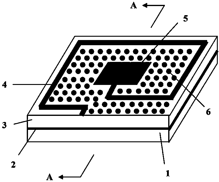
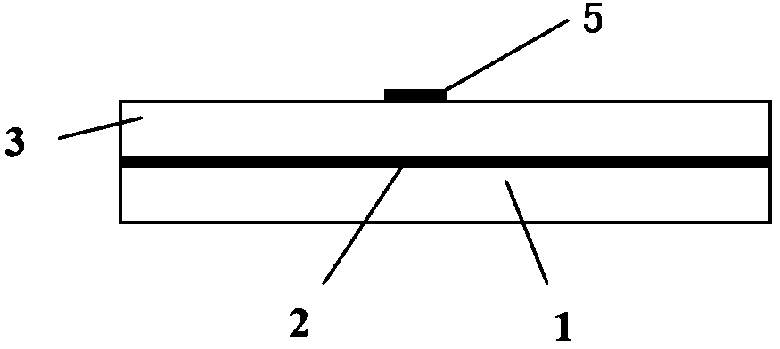
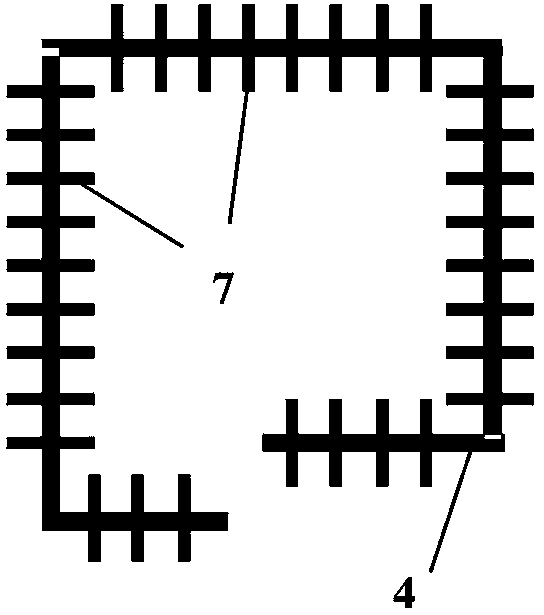
[0025] Such as figure 1 and figure 2 As shown, the present invention includes a substrate 1, a metal ground plane 2, and a ferroelectric dielectric layer 3 stacked together from bottom to top, and also includes a signal transmission line 4 and a radiation patch 5 arranged on the ferroelectric dielectric layer 3 .

[0026] The present invention adopts the ferroelectric film as the ferroelectric dielectric layer 3, and changes the dielectric constant of the ferroelectric dielectric layer 3 by changing the DC bias voltage loaded between the signal transmission line 4 and the metal ground plane 2, thereby changing the electromagnetic wave in the transmission line. The propagation speed in the medium directly realizes the phase tuning of the electromagnetic wave signal supplied to the antenna. Specifically, this is achieved: the propagation spee...


PUM


Abstract

The invention discloses a microstrip antenna with the phase shifting function. The microstrip antenna comprises a substrate, a metal ground plane, a signal transmission line and a radiation patch, wherein the metal ground plane is located on the upper surface of the substrate. The microstrip antenna further comprises a ferroelectric dielectric layer, the metal ground plane is located on the lower surface of the ferroelectric dielectric layer, the signal transmission line is attached to the upper surface of the ferroelectric dielectric layer, and a direct-current bias voltage and a high-frequency electromagnet wave signal are superimposed and are added between the signal transmission line and the metal ground plane. The microstrip antenna has the advantages of being simple in structure, small in high-frequency loss, low in noise, low in cost and the like.

Description

technical field [0001] The invention relates to the field of microwave radio frequency circuits, in particular to a microstrip antenna with a phase shifting function. Background technique [0002] Due to the advantages of fast scanning speed, flexible control, and high reliability, phased array antennas have been widely used in many fields such as wireless communication, detection, and detection. However, the traditional phased array antenna is to connect a phase shifter to each antenna to control the phase of the electromagnetic wave signal, so as to realize beam forming, deflection, focusing and other control. When the frequency reaches tens of gigahertz or even enters the terahertz band, connecting any signal processing device to the antenna will bring unexpected adverse effects such as large attenuation and large noise at low frequencies. Therefore, it is very important to invent an antenna with a phase shift function to establish a new type of phased array antenna. ...

Claims


Application Information

Patent Timeline
Patent Type & Authority Applications(China)
IPC IPC(8): H01Q9/04H01Q3/34
Inventor 张金英陈书明宁希池雅庆梁斌
Owner NAT UNIV OF DEFENSE TECH
Why Eureka
Try Eureka