Multistage division regenerative carbon dioxide trapping system and technology

A carbon dioxide and split regeneration technology, applied in the field of flue gas purification, can solve the problems of incomplete regeneration, increased circulating pumps, and low desorption degree, and achieve the goals of reducing desalted water consumption, reducing evaporation heat loss, and increasing rich liquid regeneration degree Effect

Active Publication Date: 2014-08-06
HUANENG CLEAN ENERGY RES INST
View PDF10 Cites 26 Cited by
  • Summary
  • Abstract
  • Description
  • Claims
  • Application Information

AI Technical Summary

Problems solved by technology

[0003] The flue gas carbon dioxide capture and recovery process based on alkaline alcohol amine absorption solvents has been mature in the chemical industry, and similar technologies have also been demonstrated in the power industry. The characteristic is that the regeneration of carbon dioxide in the solution needs to consume a large amount of steam, resulting in high energy consumption of the system. The reason is that, for the existing carbon dioxide capture technology, in the process of regeneration of carbon dioxide, due to incomplete regeneration and low desorption degree, about One-third of the carbon dioxide has not been released and re-enters the absorption section, resulting in insufficient absorption capacity of the solution. To ensure the same capture output, it is necessary to increase the circulation flow of the solution, which will increase the consumption of regeneration steam and cause circulation pump work. At the same time, in the prior art, the steam only releases heat to the solution once through the heat exchanger, and the heat is not fully utilized, which is also one of the reasons for the high energy consumption of the system

Method used


Image

  • Multistage division regenerative carbon dioxide trapping system and technology

Examples


Embodiment Construction

[0015] The implementation of the present invention will be described in detail below in conjunction with the drawings and examples.

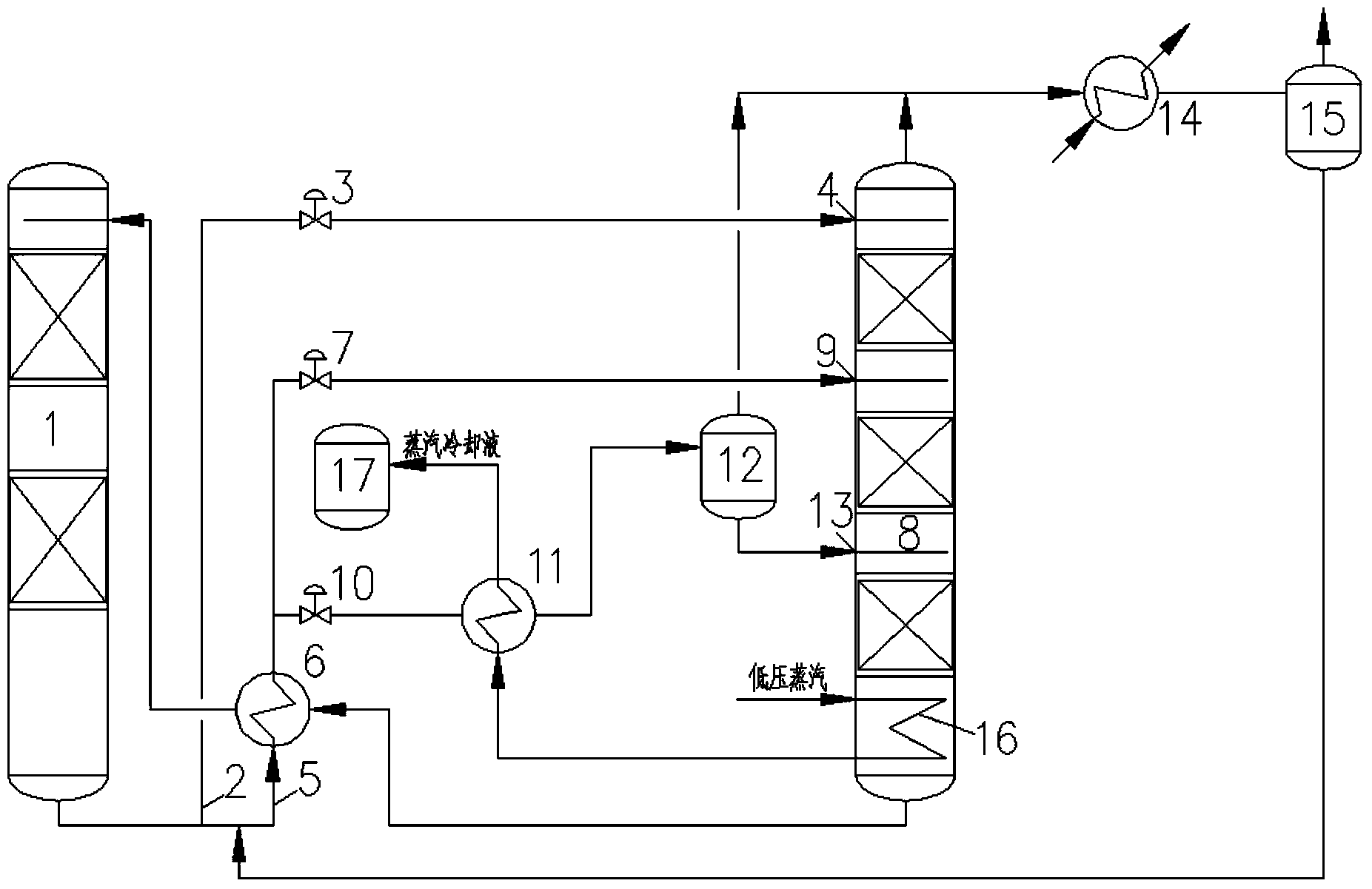
[0016] Such as figure 1 As shown, a carbon dioxide capture and treatment system for multi-stage split flow regeneration of the present invention includes an absorption tower 1, and the rich liquid coming out of the absorption tower 1 is divided into two paths, the first pipeline 2 is provided with a first regulating valve 3, and is connected with the regeneration The upper rich liquid inlet 4 of the tower 8 is connected, the second pipeline 5 is connected with the rich liquid inlet pipeline of the lean and rich liquid heat exchanger 6, and the rich liquid at the outlet of the lean and rich liquid heat exchanger 6 is divided into two paths, and one path The second regulating valve 7 is also communicated with the middle rich liquid inlet 9 of the regeneration tower 8, and the third regulating valve 10 is arranged on the other side and communicated...


PUM


Abstract

The invention relates to a multistage division regenerative carbon dioxide trapping system. The system comprises an absorption tower, wherein rich liquor that flows out of the absorption tower is divided into two channels; a first pipeline is communicated with a rich liquor inlet formed in the upper part of a regeneration tower; a second pipeline is communicated with the rich liquor inlet of a rich and poor liquid heat exchanger; rich liquor that flows out of the rich and poor liquid heat exchanger is further divided into two channels; one channel is communicated with a rich liquor inlet formed in the central part of the regeneration tower; the other channel is communicated with the rich liquor inlet of a rich liquor reheater; the rich liquor outlet of the rich liquor reheater is communicated with the rich liquor inlet of a rich liquor flash tank; the rich liquor outlet formed in the bottom of the rich liquor flash tank is communicated with a rich liquor inlet formed in the lower part of the regeneration tower. According to the invention, the regeneration degree of the rich liquor can be increased and steam heat consumption needed during rich liquor regeneration can be reduced; in addition, steam condensates can be recycled in the lyophobic collecting box of main equipment to reduce the desalted water consumption of the trapping system.

Description

technical field [0001] The invention belongs to the technical field of flue gas purification, and is especially suitable for low-concentration CO in flue gas produced by coal-fired boilers, gas turbines, and industrial furnaces. 2 capture, especially relates to a multi-stage split regeneration carbon dioxide capture system and process. Background technique [0002] The electric power and chemical industries need to consume a large amount of fossil raw materials such as coal and natural gas, and their use will bring CO 2 Mainly greenhouse gas emissions, the resulting climate change has become the focus of attention around the world. [0003] The flue gas carbon dioxide capture and recovery process based on alkaline alcohol amine absorption solvents has been mature in the chemical industry, and similar technologies have also been demonstrated in the power industry. The characteristic is that the regeneration of carbon dioxide in the solution needs to consume a large amount o...

Claims


Application Information

Patent Timeline
Patent Type & Authority Applications(China)
IPC IPC(8): B01D53/18
Inventor 牛红伟郜时旺刘练波王金意郭东方
Owner HUANENG CLEAN ENERGY RES INST
Why Eureka
Try Eureka