
Automatic heating device for special polyethylene wax for marking of road

A polyethylene wax, automatic heating technology, applied in mixers with rotary stirring devices, heat treatment, mixers, etc., can solve the problems of lack of solutions, inability to form temperature gradients, etc., saving manpower, energy, and easy heating effect of temperature

Inactive Publication Date: 2014-08-06
YANGZHOU JINXIANGSU CHEM MATERIALS FACTORY
View PDF1 Cites 2 Cited by
  • Summary
  • Abstract
  • Description
  • Claims
  • Application Information

AI Technical Summary

Problems solved by technology

However, this device can only adjust one temperature, and cannot form a temperature gradient, that is, it cannot form multiple temperatures in the heating tube to control the heating temperature
In addition, the equipment of this patented technology lacks solutions for the follow-up process, that is, how to ensure that the material always maintains a stable flow state in the feed, how to clean the tailings, etc.

Method used


Image

  • Automatic heating device for special polyethylene wax for marking of road
  • Automatic heating device for special polyethylene wax for marking of road

Examples


Embodiment 1

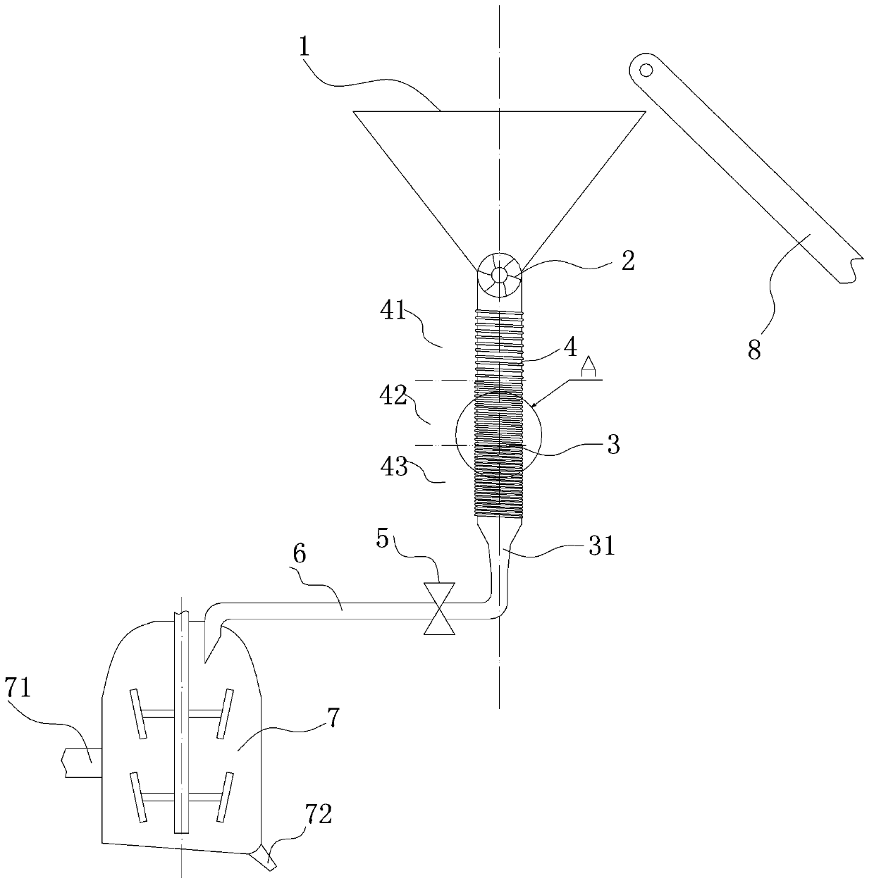
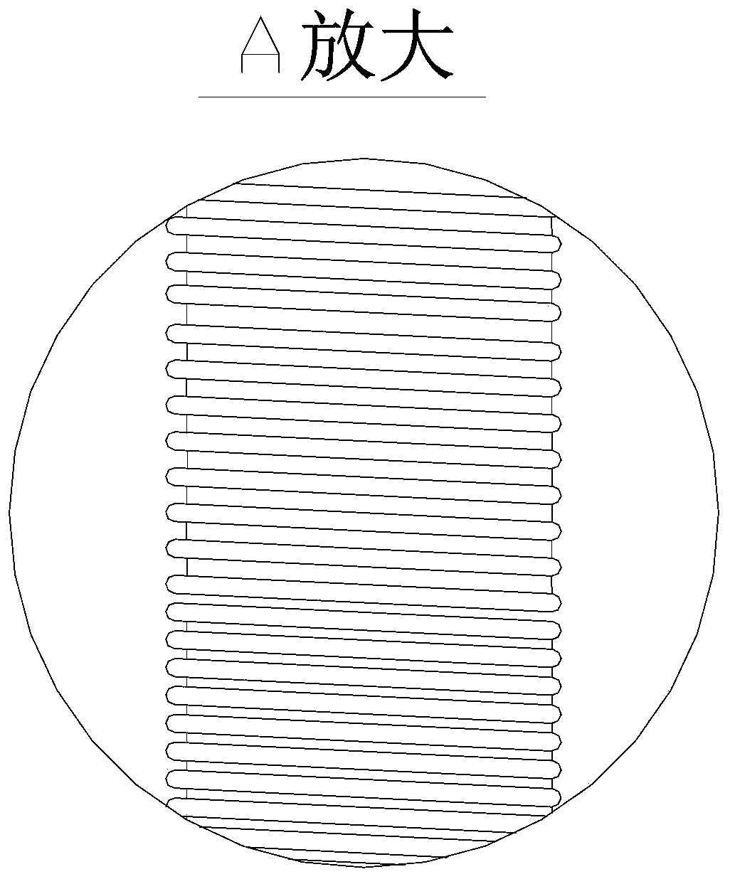
[0017] Embodiment one: if figure 1 As shown, an automatic heating device for polyethylene wax dedicated to road markings, including a conveyor belt 8, a feeding hopper 1, a feeder 2, an iron heating pipeline 3, an electromagnetic coil 4 and a fluid delivery pipe 6; The outlet of the conveyor belt 8 is connected to the upper mouth of the feeding hopper 1, and the lower mouth of the feeding hopper 1 is connected to the feed inlet of the heating pipeline 3, and the feeder 2 can be a star feeding The device is arranged at the feed inlet of the heating pipeline 1; the electromagnetic coil 4 is wound on the outer surface of the heating pipeline 3; the electromagnetic coil 4 is provided with at least two sets of coil groups with increasing temperature. For example: the electromagnetic coil 4 is provided with three sets of coil groups with increasing temperature from top to bottom, which are respectively coil group one 41, coil group two 42 and coil group three 43, and they are respec...

Embodiment 2

[0018] Embodiment 2: The difference from Embodiment 1 is that the heating pipeline is divided into four sections, which are respectively the second heating section 1, the second heating section 2, the second heating section 3 and the second heating section 4; The electromagnetic coil 4 is provided with four sets of coil groups with increasing temperature from top to bottom, which are respectively the second coil group one, the second coil group two, the second coil group three and the second coil group four, and they are respectively wound on the On the second heating section one, the second heating section two, the second heating section three and the second heating section four of the iron heating pipeline 3; the second heating section one, the second heating section two, the second heating section The temperatures of section three and second heating section four are respectively controlled at 80-90 degrees, 90-100 degrees, 120-130 degrees and 130-150 degrees.


PUM

PropertyMeasurementUnit
solidification pointaaaaaaaaaa

Abstract

The invention discloses an automatic heating device for special polyethylene wax for marking of a road, and relates to an automated heating and transmission device for the special polyethylene wax for marking of the road.. The automatic heating device can greatly improve thermal efficiency, save energy, reduce emission and reduce air pollution. The automatic heating device comprises a conveyor belt, and also a feed hopper, a feeder, an iron heating pipeline, an electromagnetic coil and a fluid-state matter conveying pipe, wherein an outlet of the conveyor belt is communicated with an upper hopper port of the feed hopper, a lower hopper port of the feed hopper is connected with a feed port of the heating pipeline, and the feeder is arranged at the feed port of the heating pipeline; the electromagnetic coil is wound on the outer surface of the heating pipeline; and an inlet of the conveying pipe is connected with a discharge port of the heating pipeline. According to the automatic heating device disclosed by the invention, as an electromagnetic heating mode convenient for heating temperature control and having high thermal effectiveness is adopted, the coal consumption caused by heating of coal is greatly reduced, 3 / 4 of the energy can be saved, and manpower can be also greatly saved by adopting an automated assembly line. By adopting a stirring kettle, liquefied special polyethylene wax can be fully and uniformly stirred and fully mixed.

Description

technical field [0001] The invention relates to an automatic heating and conveying equipment for special polyethylene wax for road markings. Background technique [0002] The special polyethylene wax for road markings plays the role of dispersing, lubricating and brightening. The current special polyethylene wax for road markings contains hardened oil with high composition and other materials. Generally speaking, the average melting point of the mixed materials is about 140-150°C, and the solidification temperature is about 70-80°C. Mixing requires special heating equipment to mix in a liquid state. Now we are using a heating boiler. The heating boiler is heated by coal or diesel oil. It consumes a lot of energy, and it is heated in units of pots. The heating pot can only heat one pot at a time, and it cannot realize automatic operation. The heating efficiency Low, and extremely unenvironmentally friendly, emitting a lot of smoke and dust. [0003] In the patent publicati...

Claims


Application Information

Patent Timeline
Patent Type & Authority Applications(China)
IPC IPC(8): B01J6/00B01F7/00B01F3/20B01F15/02B01F23/70
Inventor 曹春华
Owner YANGZHOU JINXIANGSU CHEM MATERIALS FACTORY
Learn More