Device for measuring torsional pendulum micro impulse through linear frequency modulation multi-beam laser heterodyne and torsional pendulum micro impulse measurement method based on the same

A linear frequency modulation, laser heterodyne technology, applied in measuring devices, force/torque/work measuring instruments, instruments, etc., can solve problems such as low measurement accuracy

Inactive Publication Date: 2014-08-06
HEILONGJIANG UNIV
View PDF5 Cites 4 Cited by
  • Summary
  • Abstract
  • Description
  • Claims
  • Application Information

AI Technical Summary

Problems solved by technology

[0004] In order to solve the problem of low measurement accuracy of existing devices and methods for measuring torsion micro-impulse, the present invention proposes a d

Method used


Image

  • Device for measuring torsional pendulum micro impulse through linear frequency modulation multi-beam laser heterodyne and torsional pendulum micro impulse measurement method based on the same
  • Device for measuring torsional pendulum micro impulse through linear frequency modulation multi-beam laser heterodyne and torsional pendulum micro impulse measurement method based on the same
  • Device for measuring torsional pendulum micro impulse through linear frequency modulation multi-beam laser heterodyne and torsional pendulum micro impulse measurement method based on the same

Examples


specific Embodiment approach 1

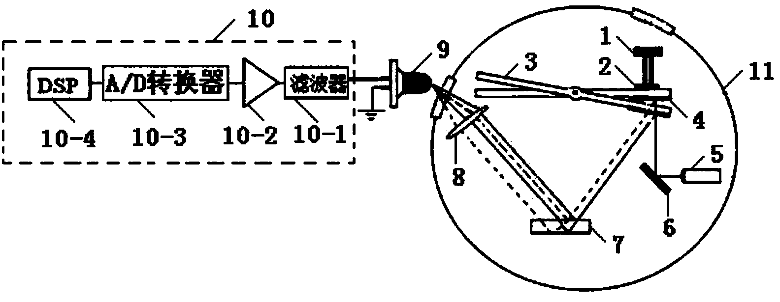
[0053] Specific implementation mode 1. Combination figure 1 Describe this specific embodiment, the device of chirped multi-beam laser heterodyne measurement torsion micro-impulse described in this specific embodiment includes chirp laser 5, first plane reflector 6, second plane reflector 4, plane standard mirror 7 , standard beam 3, vacuum chamber 11, pulsed laser 1, working fluid target 2, converging lens 8, photodetector 9 and signal processing system 10,

[0054] The chirped laser 5, the first plane reflector 6, the second plane reflector 4, the plane standard mirror 7, the standard beam 3, the pulsed laser 1, the working medium target 2 and the converging lens 8 are all placed in the vacuum chamber 11,

[0055] The center of the standard beam 3 is fixed with a rotating shaft,

[0056] The working fluid target 2 is pasted on the upper surface of the standard beam 3, the second plane mirror 4 is pasted on the lower surface of the standard beam 3, and the working fluid targe...

specific Embodiment approach 2

[0058] Specific embodiment two, combine figure 1 Describe this specific embodiment. The difference between this specific embodiment and the device for measuring torsion micro-impulse by chirp multi-beam laser heterodyne described in Embodiment 1 is that the signal processing system 10 includes a filter 10-1, a pre- Amplifier 10-2, A / D converter 10-3 and DSP10-4, the electrical signal input end of filter 10-1 is connected with the electrical signal output end of photodetector 9 as the electrical signal input end of signal processing system 10, The filter signal output end of the filter 10-1 is connected with the filter signal input end of the preamplifier 10-2, and the amplified signal output end of the preamplifier 10-2 is connected with the analog signal input end of the A / D converter 10-3 , the digital signal output terminal of the A / D converter 10-3 is connected with the digital signal input terminal of the DSP10-4.

specific Embodiment approach 3

[0059] Specific embodiment three, combine figure 1 Describe this specific embodiment. The difference between this specific embodiment and the device for measuring the torsion micro-impulse by chirp multi-beam laser heterodyne described in the first specific embodiment is that the vacuum window is used to converge the light in the vacuum chamber 11 to The photosensitive surface of the photodetector 9 outside the vacuum chamber 11 .


PUM


Abstract

The invention provides a device for measuring torsional pendulum micro impulse through linear frequency modulation multi-beam laser heterodyne and a torsional pendulum micro impulse measurement method based on the device and relates to the technical field of torsional pendulum micro impulse measurement. By the adoption of the device for measuring torsional pendulum micro impulse through linear frequency modulation multi-beam laser heterodyne and the torsional pendulum micro impulse measurement method based on the device, the problem that by the adoption of an existing device and method for measuring torsional pendulum micro impulse, the measurement precision is low is solved. According to the device for measuring torsional pendulum micro impulse through linear frequency modulation multi-beam laser heterodyne and the torsional pendulum micro impulse measurement method based on the device, a laser emitted by a pulse laser device acts on a working medium target, so that plasma spray is generated, a standard beam rotates under the action of back spray, when the standard beam rotates, a linear frequency modulation laser device continuously emits linear frequency modulation lasers, the linear frequency modulation lasers are reflected by a first plane mirror and a second plane mirror and irradiate a plane standard mirror in an incidence mode, the front surface and the rear surface of the plane standard mirror both reflect the linear frequency modulation lasers, the linear frequency modulation lasers are focused on a photosensitive surface of a photoelectric detector through a convergent lens, the photoelectric detector sends electric signals to a signal processing system, so that the tilt angle theta' of the standard beam is obtained, and then the micro impulse I' generated by action between the lasers emitted by the pulse laser device and the working medium target is obtained according to a formula. The device for measuring torsional pendulum micro impulse through linear frequency modulation multi-beam laser heterodyne and the torsional pendulum micro impulse measurement method based on the device are suitable for torsional pendulum micro impulse measurement.

Description

technical field [0001] The invention relates to the technical field of torsion micro-impulse measurement. Background technique [0002] Laser micro-thrusters have broad and in-depth application prospects in the field of attitude and orbit control of micro-satellites. Significant advantages such as digital control have attracted extensive attention from scholars at home and abroad. The impulse is an important parameter reflecting the performance of the laser micro thruster, which is characterized by a small magnitude, about 10 -7 ~10 -5 N·s. In 1999, Phipps et al. from the Photonic Associates group proposed to use the torsion pendulum system to measure the micro-impulse generated by the laser micro-thruster, and used it to test the performance parameters of the micro-thruster; in 2002, Phipps et al. improved the torsion system, and then The domestic University of Science and Technology of China and the Institute of Equipment Command Technology have also carried out relate...

Claims


Application Information

Patent Timeline
IPC IPC(8): G01L5/00
Inventor 李彦超刘明亮高扬杨九如冉玲苓杨瑞海杜军丁群王春晖马立峰于伟波
Owner HEILONGJIANG UNIV
Why Eureka
Try Eureka