
Rotation type cavitation erosion and erosive wear synergistic testing apparatus

A technology of synergy and test equipment, which is applied in the direction of testing wear resistance, sustainable manufacturing/processing, climate sustainability, etc. It can solve the problems of long time for testing and setting up equipment, few research reports, and failure to reveal the mechanism of valve damage. , to achieve the effect of easy promotion, simple structure and optimized design

Active Publication Date: 2014-08-06
嘉兴市燕知网络科技有限公司
View PDF6 Cites 10 Cited by
  • Summary
  • Abstract
  • Description
  • Claims
  • Application Information

AI Technical Summary

Problems solved by technology

[0006] (1) At present, the research on the mechanism of multiphase flow wear in my country is not deep enough, and it takes a long time to set up related equipment, so it is difficult to extend the experimental results to engineering applications
[0007] (2) Many studies are limited to the study of a single wear form of scouring wear or cavitation damage, and there are few reports on the synergistic effect of the two wear forms, which cannot reveal the damage mechanism of valves and other hydraulic machinery under the two failure forms

Method used


Image

  • Rotation type cavitation erosion and erosive wear synergistic testing apparatus
  • Rotation type cavitation erosion and erosive wear synergistic testing apparatus
  • Rotation type cavitation erosion and erosive wear synergistic testing apparatus

Examples


Embodiment 1

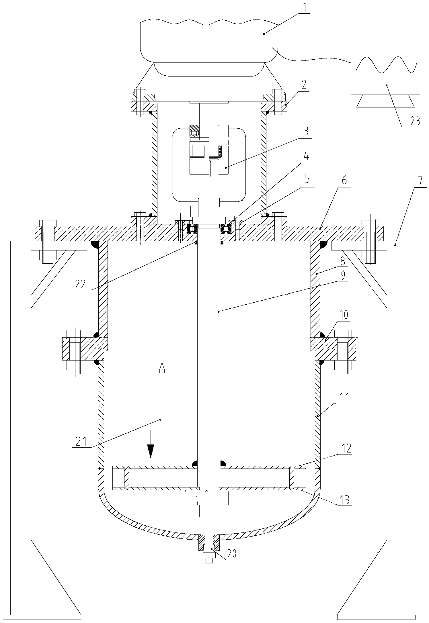
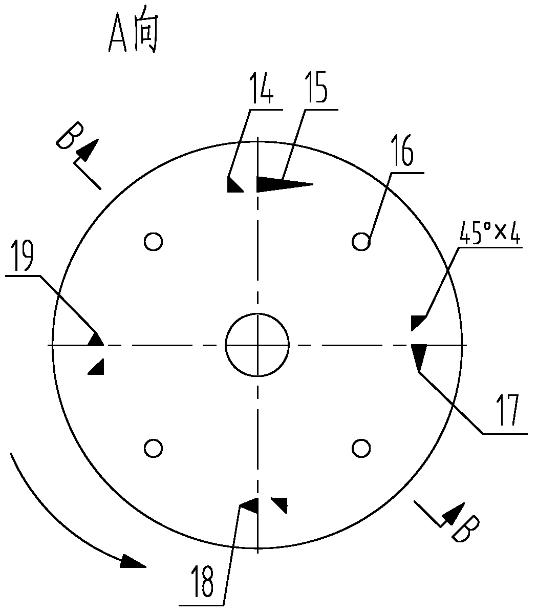
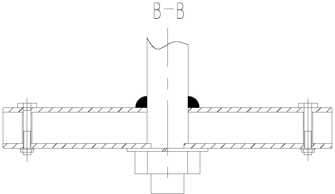
[0025] Such as figure 1 As shown, the liquid-solid two-phase flow wear test device is installed. At the beginning of the experiment, the slurry tank 11 is placed on the forklift, and the prepared fluid medium 21 of a certain concentration, such as coal-water slurry, oil-coal slurry or water mortar etc., pour in the slurry tank 11, and the liquid level has not passed the upper cover plate 12 of the turntable by about 20cm. According to the experimental plan, select four test pieces 14 that have been numbered, wipe the surface clean with alcohol, weigh them five times with an electronic balance, record the original weight, and calculate the average value Insert the test piece 14 and the cavitation inducers 15, 17, 18 and 19 into the grooves of the upper cover plate 12 of the turntable, then install the lower cover plate 13 of the turntable, and fasten the upper cover plate 12 of the turntable with four evenly distributed bolts 16 and the lower cover plate 13 of the turntable; ...

Embodiment 2

[0031] Like Example 1, only the oil-coal slurry, water-coal slurry or water mortar used in the fluid medium 21 in Example 1 is changed to clear water medium, and the cavitation inducers 15, 17, 18 and 19 at different angles can be installed. Cavitation weight loss test.

[0032] When testing in different experimental working conditions, the speed r of the variable frequency motor 1, the angle θ of the specimen 14, the cavitation time t, the density ρ of the liquid, and the cavitation number σ can be changed respectively, so as to realize the cavitation inducer 15, The cavitation weight loss rate test of the fluid medium 21 under the induction of 17, 18 and 19, so as to establish the functional relationship between different influencing factors and the cavitation weight loss rate, that is, the weight loss rate is expressed as:

[0033] ϵ 2 = k · f ( r , ...

Embodiment 3

[0035] Like Example 1, only the cavitation inducers 15, 17, 18 and 19 in Example 1 are removed, and the fluid medium 21 still uses oil-coal slurry, water-coal slurry or water mortar to carry out the erosion of the test piece 14 wear test.

[0036] When testing in different experimental conditions, the speed r of the variable frequency motor 1, the angle θ of the specimen 14 and the wear time t, the concentration w of the fluid medium 21, the density ρ of the liquid, the shape factor δ of solid particles, and the Particle size d. Thus, the functional relationship between different influencing factors and the wear rate is established, that is, the wear rate is expressed as:

[0037] ϵ 3 = k · f ( r , θ , t , w , ρ , δ , ...


PUM


Abstract

The invention discloses a rotation type cavitation erosion and erosive wear synergistic testing apparatus. A variable frequency motor is mounted at the upper end of a bell housing; the upper end of a stirring shaft is connected with the rotating shaft of the variable frequency motor through a coupler; the lower end of the stirring shaft penetrates through an upper cover plate and a lower cover plate of a turntable to be fixed; isosceles triangular test piece mounting grooves are uniformly distributed in the positions, which are located between the upper cover plate and the lower cover plate of the turntable and are 5 / 6 away from the circumferential radius; basic angles of the isosceles triangular test pieces are 45 degrees each; the vertical angles of the test piece mounting grooves face up and are identical in orientation; isosceles triangular cavitation induction unit grooves with different vertical angles are uniformly distributed in the positions which are located between the upper cover plate and the lower cover plate of the turntable and are 5 / 6 away from the circumferential radius at the interval of 90 degrees; the vertical angles of the isosceles triangular cavitation induction unit grooves are identical in orientation, and are opposite to the orientation of the vertical angles of the test piece mounting grooves; the test pieces with the same structure are respectively mounted in the test piece mounting grooves anticlockwise in the angles of 5 degrees, 95 degrees, 185 degrees and 275 degrees. The rotation type cavitation erosion and erosive wear synergistic testing apparatus disclosed by the invention can be applied to failure analysis, wear rate test, risk inspection and service life prediction for cavitation erosion and erosive wear damage of valves in the field of coal chemical industry.

Description

technical field [0001] The invention relates to a multiphase flow wear test device, in particular to a rotating cavitation and erosion wear synergy test device. Background technique [0002] Regulating valves are usually installed directly on system pipelines, and are widely used in process industries such as petroleum, coal chemical industry, and chemical fiber, and play a very important role in the development of the national economy. [0003] The study found that the failure forms of control valves are various and the mechanism is complex, among which the valve failure caused by erosion wear and cavitation (cavitation erosion) damage is the most common and common failure form of control valves in the process of throttling. Erosion wear damage has obvious locality, suddenness and risk, especially the wear thinning caused by the flow of solid particles and multiphase flow medium is more complicated and difficult to predict; cavitation damage is caused by the valve downstrea...

Claims


Application Information

Patent Timeline
IPC IPC(8): G01N3/56
CPCY02P20/10
Inventor 金浩哲偶国富肖定浩
Owner 嘉兴市燕知网络科技有限公司
Learn More