Digital triggering system of oscilloscope

A digital oscilloscope and digital comparison technology, applied in the direction of digital variable display, etc., can solve the problems of large correlation of hardware circuits, limitation of sensitivity of analog trigger system, and offset of displayed waveform relative to trigger point, etc.

Active Publication Date: 2014-08-06
CHINA ELECTRONIS TECH INSTR CO LTD
View PDF5 Cites 16 Cited by
  • Summary
  • Abstract
  • Description
  • Claims
  • Application Information

AI Technical Summary

Problems solved by technology

Inaccurate TDC measurement results will cause individual displayed waveforms to deviate from the trigger point
Random components of TDC error cause this offset to vary on each trigger event, causing trigger jitter
[0007] The main problems of the analog trigger system are that the trigger jitter always exists, and it is closely related to the hardware circuit; even if a part

Method used


Image

  • Digital triggering system of oscilloscope
  • Digital triggering system of oscilloscope

Examples


Embodiment 1

[0023] The invention provides a digital oscilloscope trigger system, which uses digital trigger technology and a digital signal processing method to measure trigger points, and detects effective trigger events with precise algorithms. Unlike analog triggering, digital triggering systems work directly on the samples from the A / D converter. The measurement signal is not split into two paths. Therefore, digital triggering processes the same signal that is acquired and displayed. The digital trigger system is mainly realized in FPGA (XC5VLX110-1FFG676).

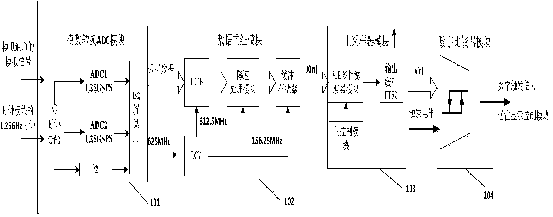
[0024] The digital trigger system of the digital oscilloscope proposed by the present invention can be applied in the hand-held digital oscilloscope with 200MHz bandwidth and 2.5GSa / s sampling rate. The digital trigger system of the present invention mainly includes an analog-to-digital conversion ADC module, a data reorganization module, an upsampler, The digital comparator consists of four parts.

[0025] The analog-to-digit...

Embodiment 2

[0030] On the basis of the above examples, if figure 1 As shown, the present invention provides a digital oscilloscope trigger system, wherein, it is composed of an analog-to-digital conversion ADC module 101, a data recombination module 102, an upsampler module 103, and a digital comparator module 104 and is connected in sequence; the analog-to-digital conversion ADC Module 101 is used to convert the analog signal transmitted by the analog channel of the oscilloscope into a digital signal to generate sampling data with a sampling rate of 2.5GSa / s. The clock generation module outside the system is used to provide a 1.25GHz synchronous clock for the trigger system of the digital oscilloscope , the 1.25GHz clock signal is sent to the clock distribution module in the analog-to-digital conversion ADC module 101, and the 0° and 180° phase difference clock signals of 1.25GHz are sent to two 1.25GSa / s sampling rate modulus respectively Cross-sampling is performed in the conversion AD...


PUM


Abstract

The invention provides a digital triggering system of an oscilloscope. An ADC module is used for converting analog signals from an analog channel of the oscilloscope into digital signals. A data reconstitution module is used for receiving four 8-bit 625 Mbps data streams output by the ADC module in parallel and outputting x(n) to an up-sampler module in a buffering storage mode. The up-sampler module is used for receiving signals x(n) of the data reconstitution module, so that pixel points of a screen and waveform sampling points are kept consistent. A digital comparator compares signals y(n) output by an up-sampler with a specified triggering threshold value ranging from 0 to 255, an output level is changed, and triggering signals are output. By the adoption of the scheme, the digital triggering system is completely achieved in an FPGA; by the adoption of the digital interpolation mode, the precision of time interval measurement is improved, triggering jittering of the oscilloscope is reduced, and the processing speed and the refresh rate are greatly increased under the circumstance that digital post-processing compensation for jittering is not needed.

Description

technical field [0001] The invention belongs to the technical field of digital oscilloscope testing, in particular to a digital oscilloscope trigger system. Background technique [0002] In the traditional analog trigger system, signal acquisition and triggering are divided into two paths. Since the delay and amplitude of the two paths are different, there will always be jitter changes in the display results at the trigger point; at the same time, most analog trigger systems use analog comparison. Comparator and high-speed logic gate circuit implementation, the layout area of ​​the device is large, the heat generated by the device is high, and the power consumption of the whole machine is large; due to the influence of noise signals, the traditional analog comparator needs to add a hysteresis circuit to obtain a stable display waveform, but there are limitations The trigger sensitivity of the analog trigger system is improved. [0003] The trigger system of a digital oscill...

Claims


Application Information

Patent Timeline
IPC IPC(8): G01R13/02
Inventor 刘洪庆张成森郭同华陈秋伟姜正吉
Owner CHINA ELECTRONIS TECH INSTR CO LTD
Why Eureka
Try Eureka