Constant current loop

A constant current loop and current detection technology, which is applied in the direction of instruments, control/regulation systems, and adjustment of electrical variables, can solve problems such as unfavorable system imbalance detection accuracy, and achieve low implementation costs, simplified loop structure, and high precision. Effect

Active Publication Date: 2014-08-06
SANECHIPS TECH CO LTD
View PDF6 Cites 2 Cited by
  • Summary
  • Abstract
  • Description
  • Claims
  • Application Information

AI Technical Summary

Problems solved by technology

[0008] The technical problem to be solved by the present invention is to provide a constant current loop to solve the problem in the prior art that at least one stage of error amplifier is required to form a constant current loop, which is not conducive to reducing system imbalance and improving detection accuracy.

Method used


Image

  • Constant current loop
  • Constant current loop
  • Constant current loop

Examples


Embodiment Construction

[0032] The present invention will be described in further detail below in conjunction with the accompanying drawings and embodiments. It should be understood that the specific embodiments described here are only used to explain the present invention, not to limit the present invention.

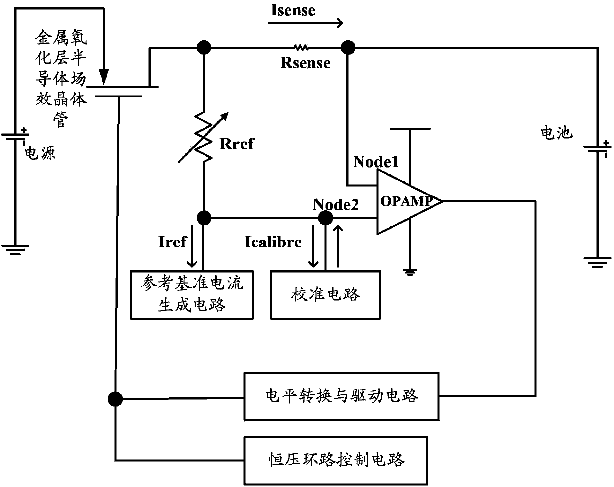
[0033] Such as figure 2 As shown, the embodiment of the present invention relates to a constant current loop, including:

[0034] An error amplifier, one end of which is connected to one end of the current detection element; the other end is connected to the other end of the current detection element through a reference generating element; the current detection element is a resistor Rsense, or an equivalent resistance realized by other components; the Rsense current detection element is used to convert the current into a voltage across the element. Use the current detection element to generate the sampling voltage as the circuit input; the reference generation element can be a resistor Rref...


PUM


Abstract

The invention discloses a constant current loop, which comprises an EA (error amplifier) and a power supply, wherein one end of the EA is connected with one end of a current detection element, and the other end of the EA is connected with the other end of the current detection element through a reference generation element; one end of the power supply is grounded, and the other end of the power supply is connected with the source or drain of a metal oxide layer semiconductor field effect transistor; the drain or source of the metal oxide layer semiconductor field effect transistor is connected with the other end of the current detection element. According to the constant current loop, the EA is directly used for forming a negative feedback closed loop, and the whole loop has only one EA gain stage; the offset voltage and bias current of the whole loop are reduced, so that constant current is higher in accuracy; in addition, the structure of the loop is simplified, and the implementation cost is lowered.

Description

technical field [0001] The invention relates to the field of battery technology, in particular to a constant current loop applied in the field of power management or current detection. Background technique [0002] Such as figure 1 As shown, the current implementation of high-precision constant current loop or current detection circuit is: through the operational amplifier and R1, R2, R3, R4 to form a closed-loop negative feedback (where R1=R3; R2=R4), sampling the current detection element The voltage drop across Rsense is amplified, and the output is at Vout. [0003] The closed loop gain is: [0004] A closed = V out V sense = R 2 R 1 ( R 1 = R 3 ...

Claims


Application Information

Patent Timeline
Patent Type & Authority Applications(China)
IPC IPC(8): G05F1/56
CPCG05F1/575G05F1/56
Inventor 胡劼
Owner SANECHIPS TECH CO LTD
Why Eureka
Try Eureka