
Active valley-filled alternating-current and direct-current converter for improving power factor efficiency

A technology of AC-DC conversion and power factor, which is applied in the electronic field and can solve problems such as cost increase and efficiency decrease

Active Publication Date: 2014-08-06
邳州市景鹏创业投资有限公司
View PDF7 Cites 11 Cited by
  • Summary
  • Abstract
  • Description
  • Claims
  • Application Information

AI Technical Summary

Problems solved by technology

These methods also introduce some problems respectively, such as: the efficiency drops due to the power dissipation of the current limiting resistor; the cost increases due to the introduction of the active switching network, etc.

Method used


Image

  • Active valley-filled alternating-current and direct-current converter for improving power factor efficiency
  • Active valley-filled alternating-current and direct-current converter for improving power factor efficiency
  • Active valley-filled alternating-current and direct-current converter for improving power factor efficiency

Examples


Embodiment 1

[0055] Embodiment 1, as Figure 9 shown in Figure 7 The specific bidirectional switch K and the corresponding control circuit are given on the basis of .

[0056] The details are as follows: an active valley-filling AC-DC converter with high efficiency and high power factor, which is composed of a diode rectifier bridge 1 , a nonlinear inductor-capacitor network 2 and a subsequent switching power converter 3 . The diode rectifier bridge 1 is an AC / DC converter; the switching power converter 3 is a DC / DC converter.

[0057] The nonlinear inductance-capacitance network 2 is composed of an inductance L, an energy storage capacitor C, a resonant capacitor Cr and a switch network; the switch network is composed of a bidirectional switch K and a diode D connected in parallel;

[0058] This bidirectional switch K is served by N-channel MOSFET. The control circuit of the bidirectional switch K is composed of resistors R1, R2, R3 and PNP transistor M.

[0059] The branch formed by...

Embodiment 2

[0073] Embodiment 2, as Figure 11 shown in Figure 7 The specific bidirectional switch K is given on the basis of . This bidirectional switch K is served by a thyristor. The thyristor is triggered to turn on through its trigger circuit according to its terminal voltage. Since the thyristor is a semi-controlled control device; specifically, once the thyristor is triggered to conduct, the thyristor cannot be turned off by its trigger terminal, it is determined by the arrangement of the power circuit it uses To reduce the conduction current of the thyristor to zero, and the thyristor also needs to withstand the reverse bias voltage for a certain period of time to restore its blocking ability. Since the thyristor is a semi-controlled control device, its cost will be low, and its reliability and overload capacity will be high. If the thyristor is to be used as a switch, due to its switching characteristics, it has the following requirements:

[0074] 1. The switching frequenc...


PUM


Abstract

The invention discloses an active valley-filled alternating-current and direct-current converter improving power factor efficiency. The active valley-filled alternating-current and direct-current converter is composed of a diode rectifier bridge (1), a non-linear LC network (2) and a subsequent switch power converter (3). The non-linear LC network (2) is powered by the output of the diode rectifier bridge (1), and the subsequent switch power converter (3) is powered by the output of the non-linear LC network (2). The non-linear LC network (2) is composed of an inductor L, an energy storage capacitor C, a resonance capacitor Cr and a switching network. The switching network is formed by connecting a bilateral switch K and a diode D in parallel. A charging circuit of the energy storage capacitor C is composed of the diode rectifier bridge (1), the inductor L, the diode D, the resonance capacitor Cr and the energy storage capacitor C. A discharging circuit of the energy storage capacitor C provides energy for the subsequent switch power converter (3) through the energy storage capacitor C and the bilateral switch K.

Description

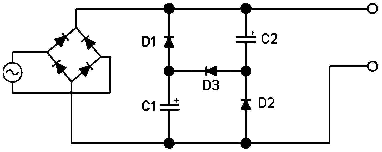
technical field [0001] The invention belongs to the field of electronic technology, and relates to AC and DC current conversion and power control. More specifically, the present invention relates to an active valley-filling AC-DC converter with high efficiency and high power factor. Background technique [0002] In the case of AC power supply, in order to achieve high power factor and meet the harmonic requirements of IEC61000-3-2, the AC-DC converter needs to implement the power factor correction function. The active boost power factor correction circuit is a very popular method, but it requires a relatively complicated control loop to control the active power switch to realize the power factor correction function, and its power factor can be greater than 0.98. In low-cost, widely used in low-power, cost-sensitive products such as energy-saving lamps and LED lighting, passive valley-filling power factor correction circuits (such as figure 1 Shown) Since there is no active...

Claims


Application Information

Patent Timeline
Patent Type & Authority Applications(China)
IPC IPC(8): H02M1/42H02M3/155
CPCY02B70/126Y02B70/10
Inventor 翁大丰魏其萃
Owner 邳州市景鹏创业投资有限公司
Learn More