Coiled material tension control system

A tension control, coil technology, applied in the direction of winding strip, thin material handling, transportation and packaging, etc., can solve the problems of limited adjustment stroke, easy material breakage, complex structure and debugging, etc.

Inactive Publication Date: 2014-08-13
福建培新机械制造实业有限公司
View PDF7 Cites 3 Cited by
  • Summary
  • Abstract
  • Description
  • Claims
  • Application Information

AI Technical Summary

Problems solved by technology

At present, the tension control methods adopted by the existing tension storage device are as follows: 1. Swing rod type storage, but the storage in this way is limited, it is difficult to adapt to the high-speed operation of the equipment when changing the material, and high-speed switching rolls cannot be realized; 2. The gravity of the hammer controls the tension of the material, but due to the influence of inertial force, the material is easy to break during the operation of the equipment
In response to these problems, the Chinese invention patent CN101767729A proposes a flexible material tension control device, but the structure and debugging of this tension control device are also relatively complicated. It is necessary to install a large wheel and a small wheel, and the cylinder piston rod is connected to the small wheel through a wire rope. Then the roller is connected to the roller through the small wheel, wheel shaft, big wheel and steel wire rope. The tension transmission path is long and the response speed is slow, and the wheel shaft connecting the big and small wheels cannot rotate for more than one circle, otherwise the potentiometer cannot feedback the signal correctly, so the adjustment stroke is affected. and the installation and commissioning of the equipment is complex and time-consuming, large and small wheels and vertical cylinders all require installation space, and the equipment takes up a lot of space

Method used


Image

  • Coiled material tension control system
  • Coiled material tension control system
  • Coiled material tension control system

Examples


Embodiment Construction

[0023] Preferred embodiments of the present invention will be described in detail below in conjunction with the accompanying drawings.

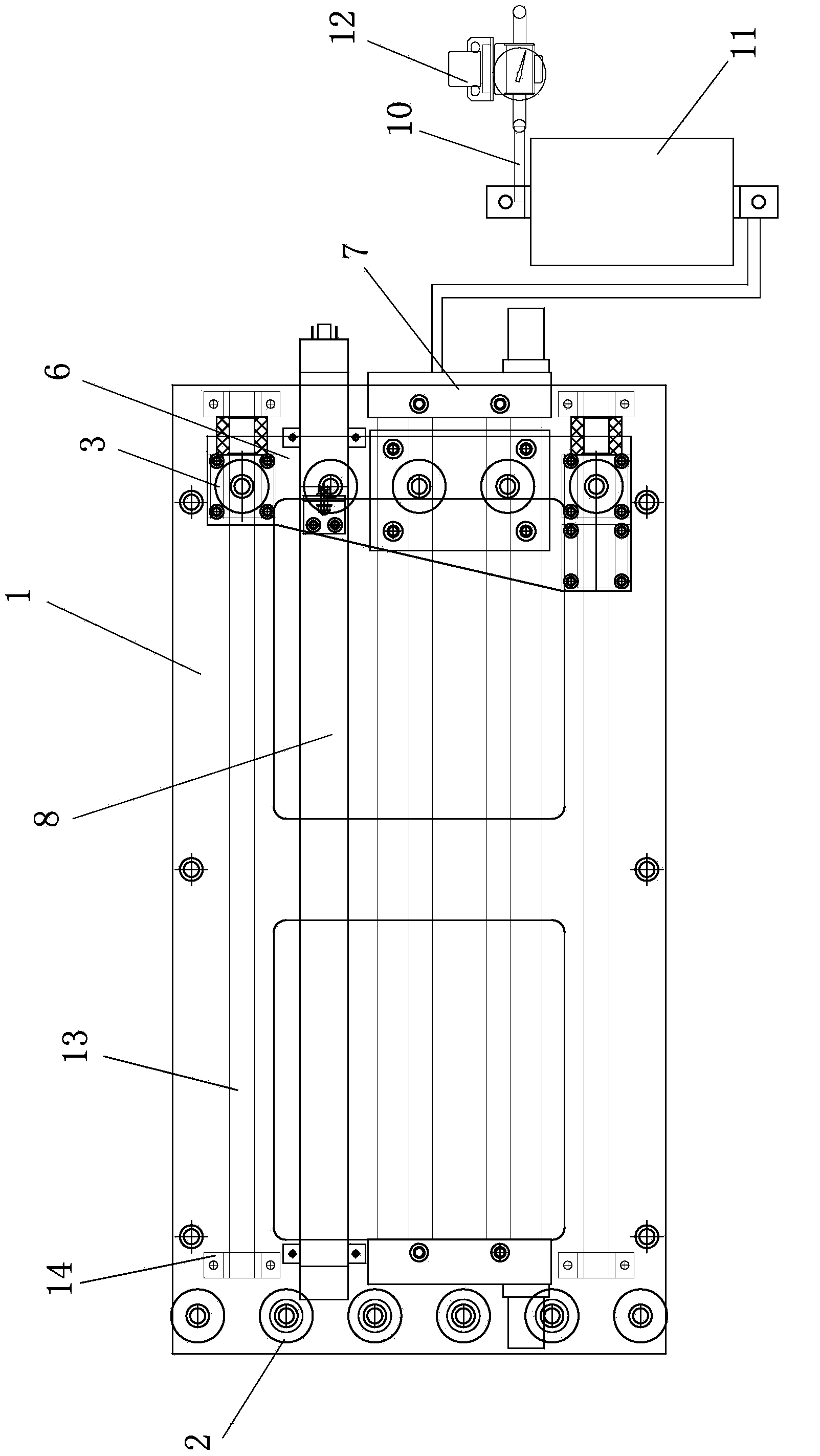
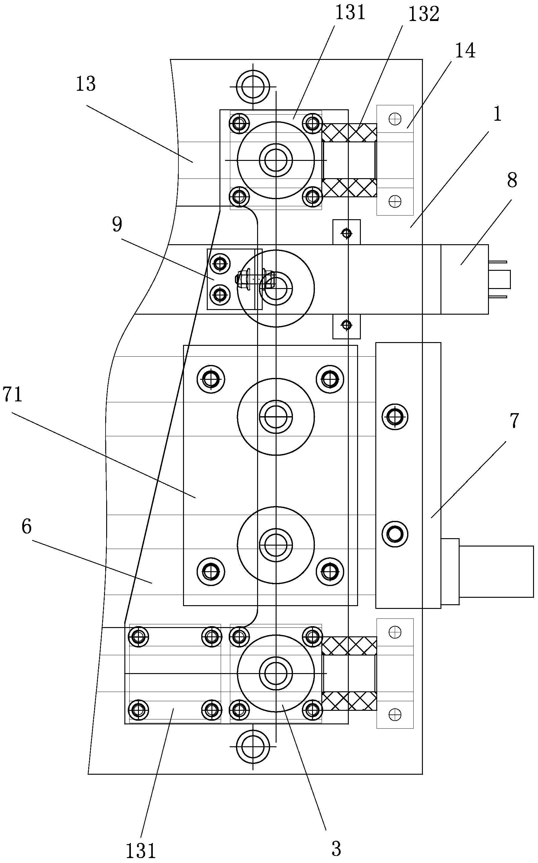
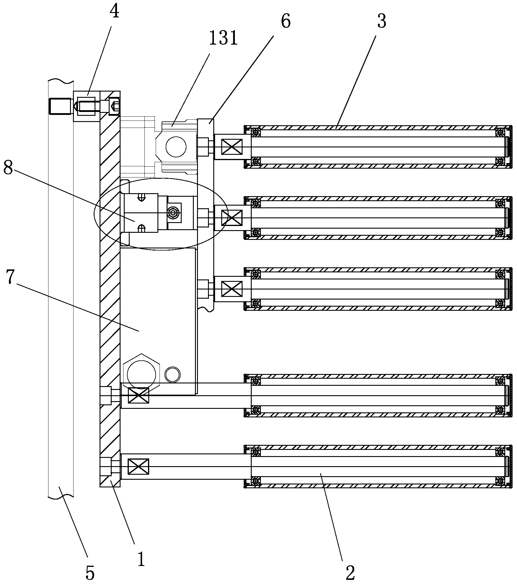
[0024] see Figure 1 to Figure 5 , a coil tension control system, comprising a fixed plate 1, a fixed roller 2 and a movable roller 3, the fixed plate 1 is installed on an upright frame wall plate 5 through a support column 4, the fixed plate 1 is a rectangular plate, and its Length is greater than height. The fixed rollers 2 and the movable rollers 3 are respectively located in groups on the left and right sides of the fixed plate 1 . The fixed rollers 2 and the movable rollers 3 are longitudinally arranged in the shape of "1", and the fixed rollers 2 and movable rollers 3 on both sides are arranged alternately in the height direction. The number of the movable rollers 3 is less than that of the fixed rollers 2, and the fixed rollers 2 pass through The shaft is rotatably fixed on the fixed plate 1 , the movable roller 3 is parallel to the ...


PUM


Abstract

The invention provides a coiled material tension control system which comprises a fixed plate, fixed rollers and movable rollers. The coiled material tension control system is characterized in that the fixed rollers and the movable rollers are respectively located on the two sides of the fixed plate in sets, one end of each movable roller is mounted on a sliding plate, a rodless air cylinder and a linear displacement sensor which are in parallel are further mounted on the fixed plate, and the sliding plate is connected with an air cylinder sliding table of the rodless air cylinder and a sliding block of the linear displacement sensor. The rodless air cylinder applies pushing force which pushes the sliding plate to be away from the fixed roller set to the sliding plate all the time, the pushing force is in balance with the preset tension of coiled materials, when the balance between the pushing force and the preset tension is broken, the sliding block moves and sends out signals to a control unit, and when the displacement of the sliding block exceeds a preset range, the control unit gives instructions to adjust the rotating speed of an unreeling motor. The coiled material tension control system is simple in structure and convenient to mount and debug, the adjusting travel is large and can be set with numerical values, the response speed is high, equipment is compact in structure and small in size, and mounting space is saved.

Description

technical field [0001] The invention relates to a flexible material production line, in particular to a coil tension control system. Background technique [0002] In the fully automatic production line of disposable household products, various flexible raw materials for the production of products are wound on rollers. During the transportation of raw materials, the tension of the materials, that is, the elongation rate, is required to be constant, otherwise the width of the materials will be uneven. even break. This requires controlling the tension of the material when it is transported on the equipment. The unwinding device of this production line is generally equipped with a tension storage device. At present, the tension control methods adopted by the existing tension storage device are as follows: 1. Swing rod type storage, but the storage in this way is limited, it is difficult to adapt to the high-speed operation of the equipment when changing the material, and high-s...

Claims


Application Information

Patent Timeline
Patent Type & Authority Applications(China)
IPC IPC(8): B65H23/26B65H23/185
Inventor 谢开达
Owner 福建培新机械制造实业有限公司
Why Eureka
Try Eureka