Oil or gas boiler

A gas-fired boiler and fuel oil technology, applied in steam boilers, fluid heaters, steam generation, etc., can solve the problems of insufficient residence time, high exhaust gas temperature, and short flue gas flow, so as to ensure self-cleaning, full fuel combustion, The effect of large furnace space

Inactive Publication Date: 2014-08-13
BRIGHT THERMAL EQUIP CO LTD
View PDF1 Cites 4 Cited by
  • Summary
  • Abstract
  • Description
  • Claims
  • Application Information

AI Technical Summary

Problems solved by technology

[0002] Oil-fired gas boilers refer to boilers that can use both fuel and gas; when the gas is insufficient or the pressure is too low, the boiler can continue to run with fuel oil without affecting the user's work process; the existing small oil-fired gas boilers tend to be quick-installed , light weight, automation; vertical boilers are widely used due to their simple structure, convenient installation and operation, and small footprint, and are widely used in the production process of small enterprises and domestic heating; however, the existing vertical oil-fired gas-fired boilers have the following features Defects: Cannot be inspected and repaired after internal problems occur; limited by the structure of the furnace, the shape of the flame cannot be fully expanded, and the combustion is insufficient; high-temperature flue gas directly washes the opposite furnace wall or base tube plate, which is likely to cause local overheating damage ; The flue gas flow is short, the residence time in the furnace is insufficient, the heat is not fully utilized, the exhaust gas temperature is high, and the thermal efficiency is low
[0003] Chinese patent application number: 02216166.X discloses a vertical fuel gas steam boiler, the smoke pipe adopts a threaded smoke pipe, and a preheating coil is arranged in the upper flue gas, and the two ends of the coil are fixed on the furnace cover , the cold water enters the water interlayer after preheating; although the problem of high exhaust gas temperature and low thermal efficiency has been solved to a certain extent by adding a preheating coil, the above problems have not been substantially improved

Method used


Image

  • Oil or gas boiler
  • Oil or gas boiler

Examples


Embodiment Construction

[0020] The present invention will be further described below in conjunction with accompanying drawing:

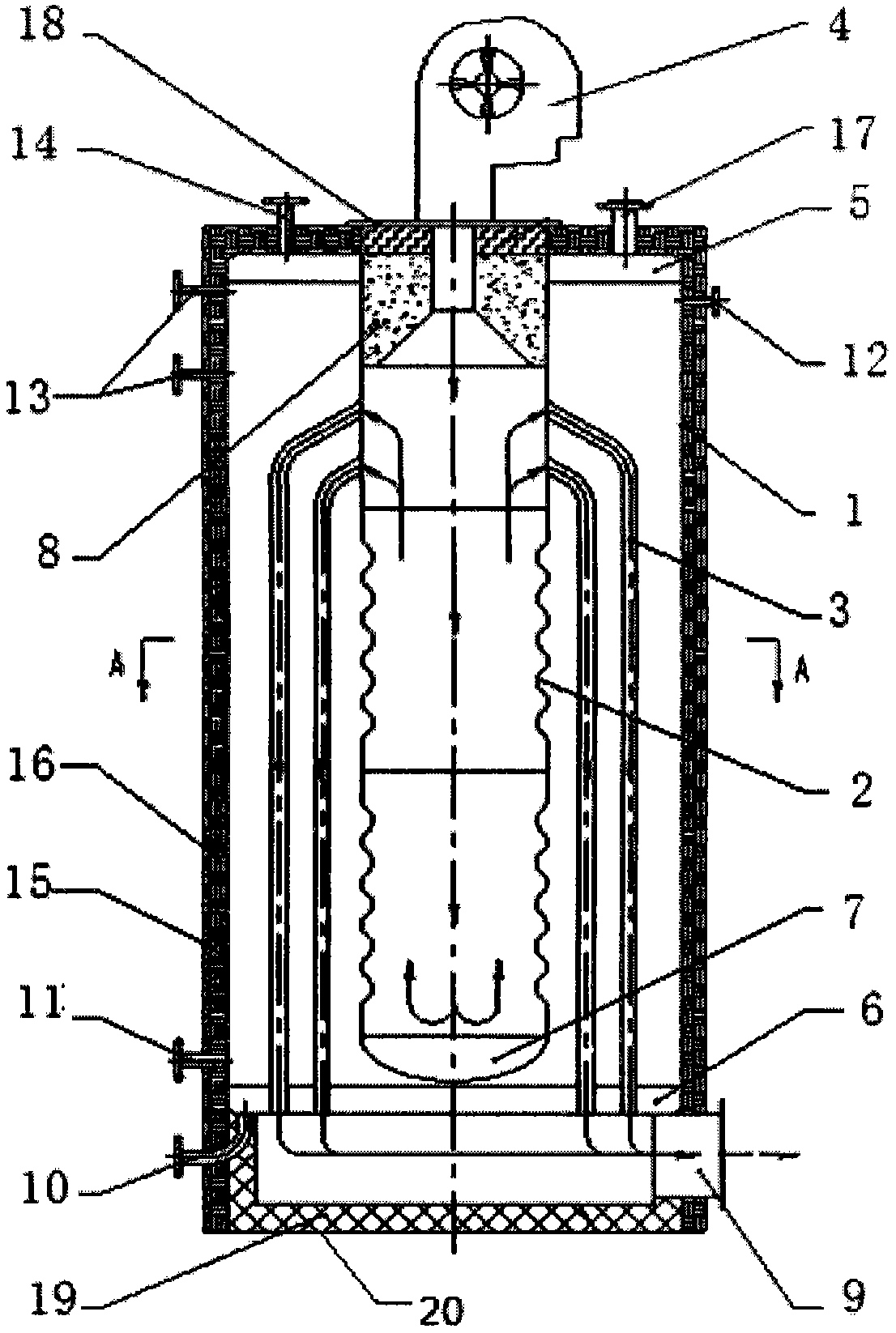
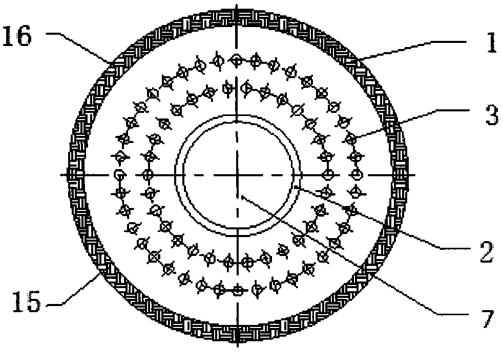
[0021] Such as figure 1 As shown, a fuel-fired gas boiler includes a pot shell 1, a furnace 2, a smoke pipe 3, a burner 4 and a pot shell base 20, and an upper tube plate 5 and a lower tube plate 6 are welded horizontally at both ends of the pot shell 2. The lower tube plate 6 is the pot shell base 20; the furnace liner 2 is a corrugated structure; the top of the furnace liner 2 is welded on the upper tube plate 5, and the bottom is welded with a head 7; the longitudinal axis of the furnace liner 2 is connected to the boiler shell 1 coincides with the longitudinal axis; the longitudinal axis of the pot shell 1 is perpendicular to the ground; the burner 4 is fixed on the tile mouth 8 of the furnace liner by fasteners and the burner interface flange 18; the upper end of the furnace liner 2 and The lower tube plate 6 is provided with two rows of through holes arranged at inte...


PUM


Abstract

The invention discloses an oil or gas boiler, comprising a boiler shell, a boiler furnace, a smoke pipe, a combustor and a boiler shell pedestal, wherein two ends of the boiler shell are respectively welded with an upper pipe plate and a lower pipe plate horizontally; the lower side of the lower pipe plate is connected with the boiler shell pedestal in a welding way; the boiler furnace is of a waveform structure; the upper side of the boiler furnace is welded on the upper pipe plate; the lower side of the boiler furnace is welded with an end socket; the combustor is fixedly arranged on the tile edging of the boiler furnace through a fastener and a combustor interface flange; two rows of through holes arranged at interval are formed in each of the upper end of the boiler furnace and the lower pipe plate; the smoke pipe serves as a spiral smoke pipe; two ends of the smoke pipe are welded at the through holes in the upper end of the internal furnace and at the through holes in the lower pipe plate in a way of corresponding arrangement. By applying the oil or gas boiler provided by the invention, the flame is completely spread; the combustion is full; the smoke flow path is long; the heat exchange efficiency is high.

Description

technical field [0001] The invention belongs to the field of oil-fired gas boilers, and in particular relates to a vertical wet-back central flame-return oil-fired gas boiler. Background technique [0002] Oil-fired gas boilers refer to boilers that can use both fuel and gas; when the gas is insufficient or the pressure is too low, the boiler can continue to run with fuel oil without affecting the user's work process; the existing small oil-fired gas boilers tend to be quick-installed , light weight, automation; vertical boilers are widely used due to their simple structure, convenient installation and operation, and small footprint, and are widely used in the production process of small enterprises and domestic heating; however, the existing vertical oil-fired gas-fired boilers have the following features Defects: Cannot be inspected and repaired after internal problems occur; limited by the structure of the furnace, the shape of the flame cannot be fully expanded, and the ...

Claims


Application Information

Patent Timeline
Patent Type & Authority Applications(China)
IPC IPC(8): F22B31/00F24H1/22F24H9/18
Inventor 郭辉
Owner BRIGHT THERMAL EQUIP CO LTD
Why Eureka
Try Eureka