Drill bits for drilling large diameter piles in bridge foundations

A bridge foundation and large-diameter technology, applied in the direction of drill bits, drilling equipment, earthwork drilling and mining, etc., can solve the problems of limited suction force of a single slag suction port, affecting the drilling efficiency of the drill bit, repeated crushing of rock slag, etc., to reduce repeated crushing , Improve the rock-breaking ability and slag discharge efficiency, and improve the effect of the stress condition

Active Publication Date: 2016-07-13
梁振西
View PDF5 Cites 0 Cited by
  • Summary
  • Abstract
  • Description
  • Claims
  • Application Information

AI Technical Summary

Problems solved by technology

This structure mainly has the following deficiencies: 1. Since the hob and the hob tool holder assembly are in the same form and are arranged in a straight line, the axis of each hob cutter shaft and the cutter body on the drill bit will not The intersection point of the busbar is not on the central axis of the cutterhead body, which causes the cone angle of the hob busbar to overshoot or shrink. The force in the rock breaking process is more complicated, and the rock breaking cannot be rolled well; 2. Single slag suction The suction force of the suction port is limited, and the rock slag broken by the hob during construction cannot be discharged through this slag suction port in time, resulting in repeated crushing of the rock slag, which affects the drilling efficiency of the drill bit

Method used


Image

  • Drill bits for drilling large diameter piles in bridge foundations
  • Drill bits for drilling large diameter piles in bridge foundations
  • Drill bits for drilling large diameter piles in bridge foundations

Examples


Embodiment 1

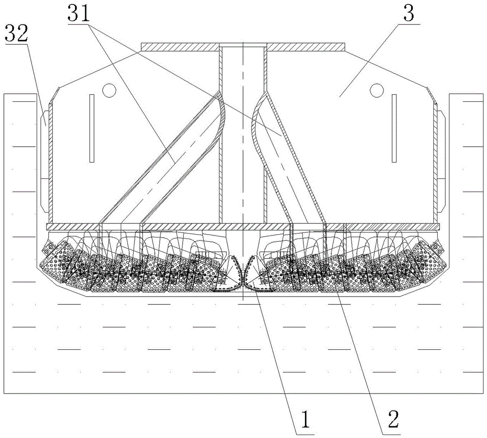
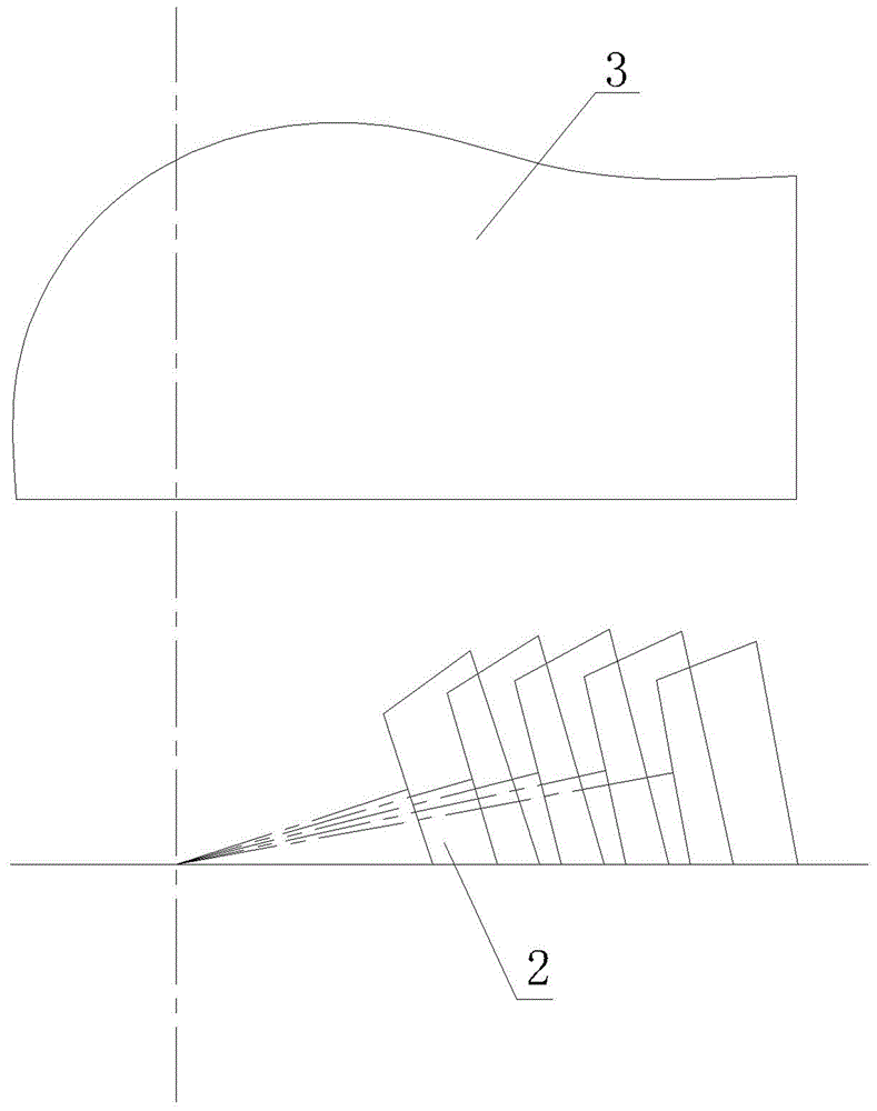
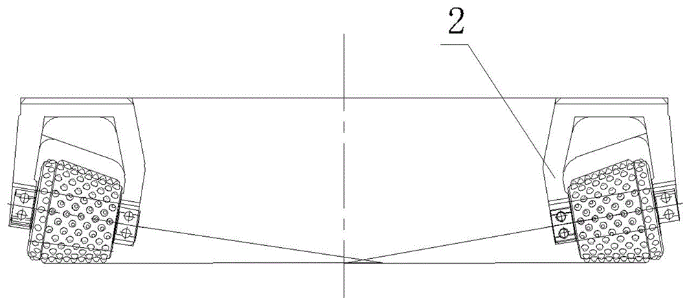
[0027] From Figure 1 to Figure 3 It can be seen that the drill bit used for drilling large-diameter piles of bridge foundations according to the present invention includes two single-support ball-tooth hobs 1, several hobs and hob tool holder assemblies 2 and cutterhead body 3, each hob The hob on the hob and hob tool holder assembly 2 adopts a ball-tooth shape, and two slag suction ports 31 are provided on the cutter head body 3. 2. Indirect welding under the cutterhead body 3 by means of electric welding through the backing plates corresponding to each cutter holder to form a flat-bottomed rolling section. The angle between them decreases in turn along the radial direction of the cutter body 3 from its axis to the surroundings. The axis of the hob cutter shaft and the cutter body The intersection points of the busbars intersect on the central axis of the cutter head body 3 to form a pure rolling rock breaking.

Embodiment 2

[0029] From Figure 4 to Figure 6 It can be seen that the drill bit used for drilling large-diameter piles of bridge foundations according to the present invention includes two single-support ball-tooth hobs 1, several hobs and hob tool holder assemblies 2 and cutterhead body 3, each hob The hob on the hob and hob tool holder assembly 2 adopts a welding tooth shape, and two slag suction ports 31 are provided on the cutter head body 3. 2. Indirect welding under the cutterhead body 3 by means of electric welding through the backing plates corresponding to each cutter holder to form a flat-bottomed rolling section. The angle between them decreases in turn along the radial direction of the cutter body 3 from its axis to the surroundings. The axis of the hob cutter shaft and the cutter body The intersection points of the busbars intersect on the central axis of the cutter head body 3 to form a pure rolling rock breaking.

Embodiment 3

[0031] From Figure 7 to Figure 9 It can be seen that the drill bit used for drilling large-diameter piles of bridge foundations according to the present invention includes two single-support ball-tooth hobs 1, several hobs and hob tool holder assemblies 2 and cutterhead body 3, each hob and the hob on the hob tool holder assembly 2 adopts a button shape, and two slag suction ports 31 are arranged on the cutter head body 3, and several backing plates 33 are arranged obliquely at the bottom of the cutter head body 3, each The single fulcrum ball tooth hob 1 and the hob and hob tool holder assembly 2 are welded under the corresponding backing plate 32, and the rolling section of each hob and hob cutter holder assembly 2 intersects with the axis of the cutter head body 3 to form a A conical rolling section, the angle between the axis of the hob cutter shaft on each hob and the hob holder assembly 2 and the generatrix of the cutter body decreases sequentially along the axis of the...


PUM


Abstract

The invention discloses a drill bit for hole drilling in a large-diameter pile of a bridge foundation. The drill bit comprises a plurality of hobs, hob seat combination pieces and hob disc bodies, and further comprises two single-supporting-point spherical tooth hobs which are symmetrically installed in the centers below the hob disc bodies, the single-supporting-point spherical tooth hobs, the hobs and the hob seat combination pieces are welded to below the hob disc bodies to form a rolling cross section, two slag sucking holes are formed in the hob disc bodies, included angles formed between axes of hob shafts on the hobs and the hob seat combination pieces and the generatrix of hob bodies are sequentially decreased from the axes of the hob disc bodies to the peripheries, and the intersection points of the axes of the hob shafts on the single-supporting-point spherical tooth hobs, the hobs and the hob seat combination pieces and the generatrix of the hob bodies are located on the axle lines of the hob disc bodies to form pure rolling type rock breaking. By means of the drill bit, the rock breaking capacity and the slagging efficiency can be effectively improved, and the drill bit is suitable for hole drilling in various rock stratums.

Description

technical field [0001] The invention belongs to the field of bridge equipment, in particular to a drill bit used for drilling large-diameter piles of bridge foundations. Background technique [0002] In the construction of large-diameter bridge foundations, the rolling drill bit is mainly composed of several hobs and hob tool holder assemblies of the same form and a cutterhead body. A slag suction port is arranged on the cutterhead body. Each hob and hob The cutter seat assembly is installed parallelly on the panel at the bottom of the cutter body in turn, and the hob rolls back and forth to form a flat-bottomed rolling section. This structure mainly has the following deficiencies: one, because the hob and the hob tool holder assembly are in the same form and are arranged in a straight line, under the condition that the lower bottom surfaces are coplanar, the axis of each hob cutter shaft and the cutter body on the drill bit The intersection point of the busbar is not on th...

Claims


Application Information

Patent Timeline
Patent Type & Authority Patents(China)
IPC IPC(8): E21B10/43E21B10/60
Inventor 梁振西金文革张念来曹奇亚
Owner 梁振西
Why Eureka
Try Eureka