
Power turbine output shaft system

A power turbine and output shaft technology, applied in engine components, machines/engines, mechanical equipment, etc., can solve the problems of lubricating oil leakage, lubricating oil leakage, pressure unbalanced lubricating oil, potential safety hazards of experimental systems, etc., to reduce heat load, strong load capacity, and the effect of ensuring thermal safety

Inactive Publication Date: 2014-08-20
TIANJIN UNIV
View PDF5 Cites 2 Cited by
  • Summary
  • Abstract
  • Description
  • Claims
  • Application Information

AI Technical Summary

Problems solved by technology

The pressure imbalance at both ends of the lubricating oil can easily cause the lubricating oil to seep out of the power output shaft end along the axial direction
The leakage of lubricating oil will not only cause the gradual reduction of the amount of lubricating oil, but also cause great hidden dangers to the safety of the experimental system.

Method used


Image

  • Power turbine output shaft system
  • Power turbine output shaft system
  • Power turbine output shaft system

Examples


Embodiment Construction

[0018] The present invention will be described in detail below in conjunction with the accompanying drawings and specific embodiments.

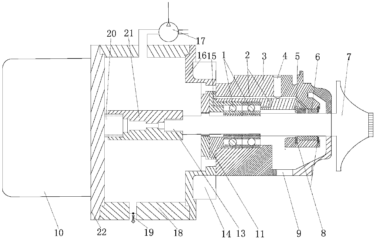
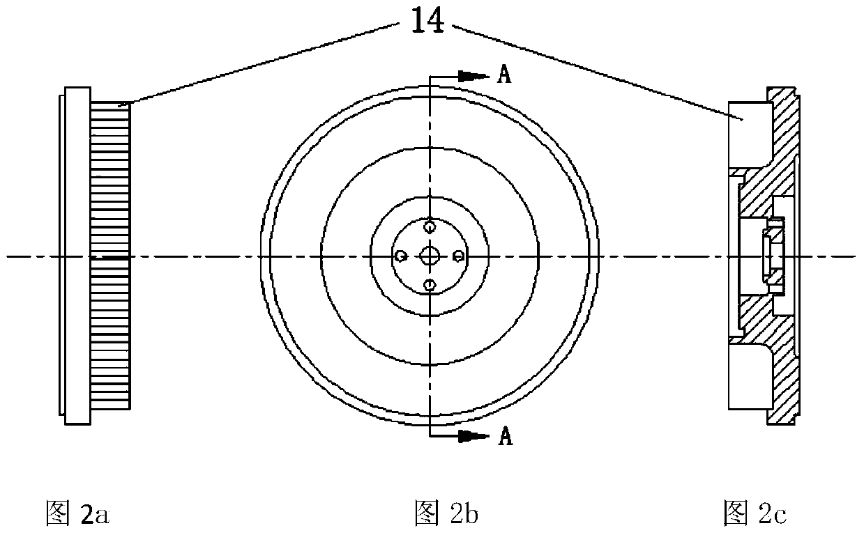
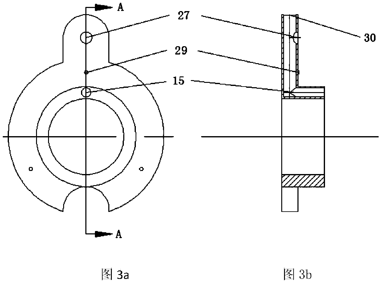
[0019] As shown in the accompanying drawings, a power turbine output shaft system of the present invention includes a floating bearing 6 arranged at the turbine end of the turbine shaft and a double parallel rolling bearing 1 arranged at the output shaft end of the turbine shaft. In the floating bearing 6 The intermediate body 3 is covered with the double parallel rolling bearing 1, and the back plate 16 fitted on the output shaft end of the turbine shaft is tightly fitted and fixed on the end surface of the intermediate body 3 on the motor side, and the bearing end cover 11 for fixing the double parallel rolling bearing 1 is fixed. Installed between the backplane and the intermediate body, between the backplane flange and the flange 22 of the motor housing 10, a sleeve 18 with positioning notches at both ends is installed, the backplane flang...


PUM

PropertyMeasurementUnit
Thicknessaaaaaaaaaa
Diameteraaaaaaaaaa
Diameteraaaaaaaaaa

Abstract

The invention discloses a power turbine output shaft system. A floating bearing and a double-parallel rolling bearing are arranged on a turbine shaft and sleeved with a middle body, a back plate is fixed to the portion, located on the motor side, of one end face of the middle body, a bearing end cover is installed between the back plate and the middle body, a closed air chamber is formed by the back plate, a flange of a motor shell and a sleeve through end face matching, a main oil way and a double-parallel rolling bearing lubricating oil way which is communicated with the main oil way are formed in the middle body, a floating bearing lubricating oil way is communicated with the double-parallel rolling bearing lubricating oil way, a rolling bearing lubricating oil way communicated with the double-parallel rolling bearing lubricating oil way is formed in the bearing end cover, lubricating oil is led from the engine side to the end face of an engine side rolling bearing through the rolling bearing lubricating oil way, and a plurality of cooling fins are arranged on the turbine side of the back plate. By means of the power turbine output shaft system, the bearings can be effectively lubricated, and meanwhile the lubricating oil can be prevented from leaking in the axial direction and thermal insulation can be effectively achieved.

Description

technical field [0001] The invention relates to a power turbine, and mainly relates to a power turbine output shaft system. Background technique [0002] Using a power turbine to recover the energy of the exhaust residual pressure of a thermomechanical machine is one of the current methods to take measures outside the machine to improve the thermal efficiency of the system. Taking a diesel engine as an example, about 30% of the fuel energy injected into the cylinder is wasted through the exhaust gas. Power turbine power generation technology or power turbine mechanical coupling technology can be used to convert the energy in the waste heat into electrical energy or mechanical energy. The converted electric energy can be incorporated into the power grid of the vehicle to meet the energy consumption requirements of the vehicle's electric accessories; the mechanical coupling of the power turbine is to reduce the speed and increase the torque through the reduction mechanism, and...

Claims


Application Information

Patent Timeline
IPC IPC(8): F01D25/00
Inventor 谢辉何冠璋
Owner TIANJIN UNIV
Learn More