Electric drive two-gear double-stage hub reduction gear

A technology of reducer and electric drive, applied in transmission elements, transmission devices, vehicle gearboxes, etc., can solve the problems of complex transmission, reduced efficiency, small vehicle ground clearance, etc., and achieve the effect of flexible overall layout and reduced turning diameter.

Active Publication Date: 2014-08-20
BEIJING INST OF SPACE LAUNCH TECH +1
View PDF7 Cites 10 Cited by
  • Summary
  • Abstract
  • Description
  • Claims
  • Application Information

AI Technical Summary

Problems solved by technology

[0002] The power transmission system of a traditional chassis is mainly composed of an engine, a gearbox, a transfer case, a final drive, and a transmission shaft. The shaft transmits the motion to each wheel, and drives the rotation of each wheel of the vehicle through a final reducer. The various components of the transmission system are relatively complicated, and the movement transmission between them is also relatively complicated, which is not conducive to the flexible layout of the vehicle.
Due to the power limitation of the engine, the structural limitation of the transmission system, and the problem of reduced efficiency caused by multi-axis long-distance transmission, it is impossible to achieve the high mobility requirements of vehicles with more than 6 axles; The wheel angle is limited, which makes the diameter of the wheel angle relatively large, which is not conducive to the turning of the vehicle; at the same time, due to the structural limitations of the transmission system, the vehicle's ground clearance is small, which limits the ability of the vehicle to cross trenches and obstacles

Method used


Image

  • Electric drive two-gear double-stage hub reduction gear

Examples


Embodiment Construction

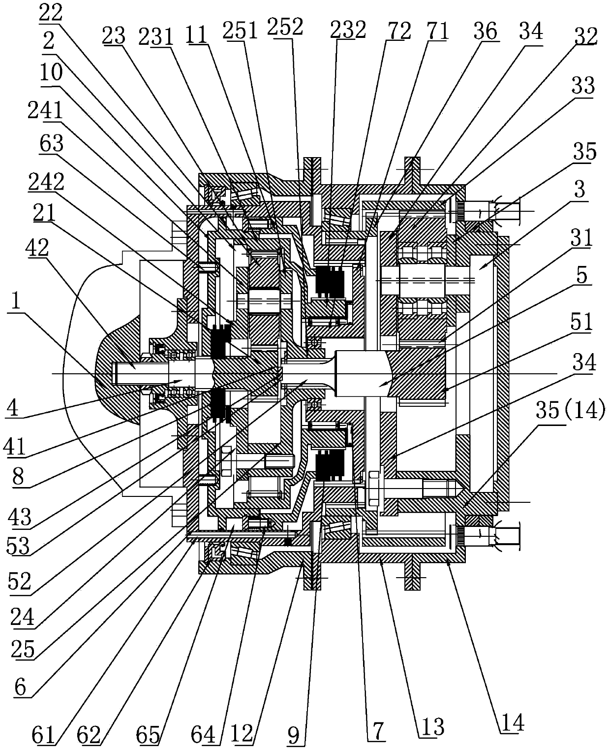
[0026] Such as figure 1 As shown, the electric drive wheel reducer of the present invention includes a motor 1, a primary planetary reduction mechanism 2 and a secondary planetary reduction mechanism 3, a reducer input shaft 4 and a reducer output shaft 5, an outer casing 6 and an inner casing 7, The first clutch 8 and the second clutch 9, the first power piston 10 and the second power piston 11,

[0027] The motor 1 is located on the left side of the outer shell 6, and the output shaft of the motor 1 is connected with the input end 42 of the reducer input shaft 4,

[0028] The first-stage planetary reduction mechanism 2 is located at the output end 41 of the input shaft 4 of the reducer, and the second-stage planetary reduction mechanism 3 is located at the output end 51 of the output shaft 5 of the reducer.

[0029] The outer casing 6 is set on the outer side of the reducer, and an oil passage 61 is arranged on the outer peripheral surface of the left side of the outer casi...


PUM


Abstract

The invention relates to a speed reducer in an automobile transmission system, and provides an electric drive two-gear double-stage hub reduction gear which is compact in transmission structure, high in transmission efficiency, flexible to arrange and capable of achieving independent drive of each wheel. The electric drive two-gear double-stage hub reduction gear comprises a primary planetary speed reduction mechanism, a secondary planetary speed reduction mechanism, a reduction gear input shaft, a reduction gear output shaft, an outer shell, an inner shell, a first clutch, a second clutch, a first oil pressure control device and a second oil pressure control device. A motor is arranged on the left side of the outer shell, an output shaft of the motor is connected with the input end of the reduction gear input shaft, the primary planetary speed reduction mechanism is arranged at the output end of the reduction gear input shaft, the secondary planetary speed reduction mechanism is arranged at the output end of the reduction gear output shaft, the transmission mode of the primary planetary speed reduction mechanism is changed through the first clutch and the second clutch, and therefore output of different speed ratios is achieved.

Description

technical field [0001] The invention relates to a speed reducer, in particular to a speed reducer used in the transmission system of an automobile. Background technique [0002] The power transmission system of a traditional chassis is mainly composed of an engine, a gearbox, a transfer case, a final drive, and a transmission shaft. The shaft transmits the motion to each wheel, and drives the rotation of each wheel of the vehicle through a final reducer. The components of the transmission system are relatively complicated, and the movement transmission between them is also relatively complicated, which is not conducive to the flexible layout of the vehicle. Due to the power limitation of the engine, the structural limitation of the transmission system, and the problem of reduced efficiency caused by multi-axis long-distance transmission, it is impossible to achieve the high mobility requirements of vehicles with more than 6 axles; The wheel angle is limited, which makes the...

Claims


Application Information

Patent Timeline
Patent Type & Authority Applications(China)
IPC IPC(8): F16H3/46
CPCF16H3/46F16H2200/0021F16H2200/2007F16H2200/2035
Inventor 赵娟魏朔李洪彪张斌谷捷杨波刘丁华
Owner BEIJING INST OF SPACE LAUNCH TECH
Why Eureka
Try Eureka