
Aging test equipment for electronic products

A technology for aging testing and electronic products, applied in the direction of measuring electricity, measuring devices, measuring electrical variables, etc., can solve the problems affecting the expansion and deepening of application fields, the failure to discover and record products in time, the stability of electrical properties, and the attenuation of light and color properties Issues such as consistency and service life

Inactive Publication Date: 2014-08-20
松阳西屏永新机械厂
View PDF6 Cites 19 Cited by
  • Summary
  • Abstract
  • Description
  • Claims
  • Application Information

AI Technical Summary

Problems solved by technology

[0002] There are many electronic products, including LED lamps, bulb lamps, mobile power supplies, adapters, etc. They are prone to aging. In the prior art, there are few aging test systems for batch and standardized testing of these electronic products.
[0003] Taking LED as an example, the LED industry is developing rapidly, and LED-related devices are relatively mature, but there is still a lack of systematic research on LED devices, especially in terms of failure mechanism, so the reliability of LEDs in design, manufacturing and application. It has always been a difficult problem in the industry, and directly affects the expansion and deepening of the application field
In lighting, display equipment and other applications, LED devices are often composed of multiple LEDs, which have very high requirements for electrical performance stability, light and color performance attenuation consistency, and service life. After working for a long time, the color temperature of each LED, Color rendering, color purity, spectral distribution, light uniformity, and illuminance will all change with time; in addition, LEDs that work normally at the initial stage of installation will appear dark, flickering, malfunctioning, Intermittent lighting and other phenomena will cause serious damage to the product
At the same time, problems such as the inability to detect and record the problematic products in time, and the damage to the body caused by the long-term work of the staff in the aging room of strong light and high temperature also need to be solved urgently.
[0004] In addition to LEDs, the aging speed of other electronic products is directly related to the product quality. Therefore, it is often necessary to test the aging degree of these electronic products. At present, the aging tests of these electronic products are tested separately, not only lack of good testing equipment , and a single piece of testing is very labor-intensive and time-consuming, and the efficiency is low. There is a lack of aging test equipment that can batch and scale multiple products.

Method used


Image

  • Aging test equipment for electronic products
  • Aging test equipment for electronic products
  • Aging test equipment for electronic products

Examples


Embodiment 1

[0026] Embodiment 1: The hardware structure of the present invention is described in combination with functions.

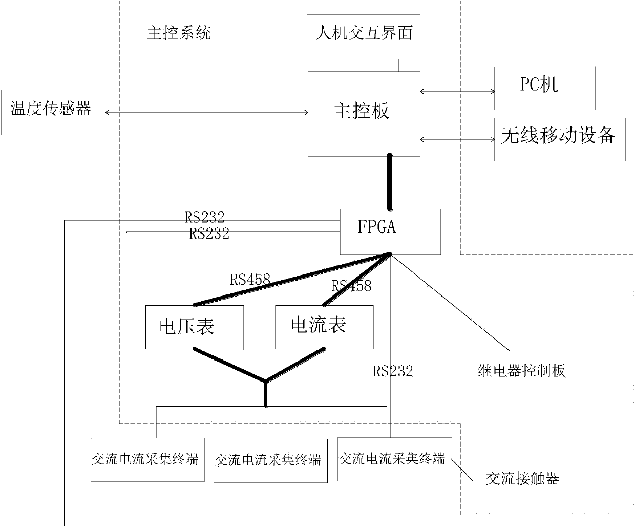
[0027] Such as figure 1 As shown, the aging test system for electronic products in this embodiment is divided into three parts: a test module, a main control system, and a monitoring terminal. The monitoring terminal is a PC and / or a mobile device, and the mobile device is a wireless mobile device. The application software is installed on the PC and / or the wireless mobile device, and the PC and the wireless mobile device have similar functions, and the PC or the wireless mobile device may be used only, or both the PC and the mobile device may be used. In the following examples, the embodiments of the present invention preferably use LEDs in electronic products as test objects.

[0028] The signal of the above test module is connected to the main control system. The test module includes a plurality of AC current acquisition terminals with LED sockets and can be co...

Embodiment 2

[0053] Embodiment 2: as figure 2 As shown, on the basis of Embodiment 1, this embodiment also adds a temperature sensor. The temperature sensor is installed in the aging test room close to the AC current collection terminal, and the temperature sensor is directly connected to the main control system. The temperature sensor senses the current temperature and inputs the temperature sensor according to the current temperature. If the temperature change exceeds the set threshold, the internal parameters are automatically adjusted to ensure the accuracy of the detection results. When the temperature exceeds the set range, the cooling device is controlled to work . All the other are identical with embodiment 1, repeat embodiment 1.

Embodiment 3

[0055] On the basis of Embodiment 2, this embodiment also adds an internal ERP system of the enterprise, and the main control system is connected to the internal ERP system of the enterprise, so as to transmit the data that the test results and alarm information are stored in the database in real time to the internal ERP system of the enterprise . All the other are identical with embodiment 2, repeat embodiment 2.


PUM


Abstract

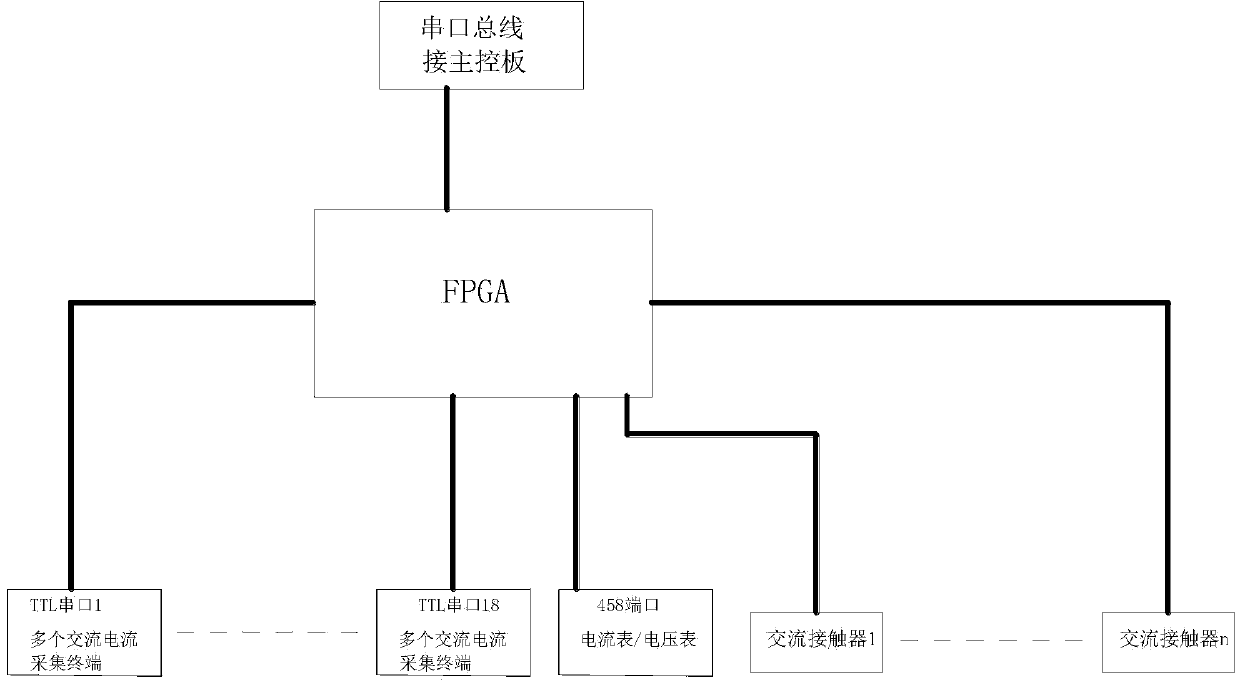
The invention particularly relates to aging test equipment for electronic products. The aging test equipment comprises a test module, a main control system and a monitoring terminal. The test module is in signal connection with the main control system, the main control system is connected with the monitoring terminal, the test module comprises a plurality of alternating-current acquisition terminals, and the main control system comprises a service processing module. The service processing module comprises a main control panel, an FPGA, an ampere meter, a voltmeter and a switch module, wherein the FPGA is respectively and electrically connected with the ampere meter and the voltmeter through ports 458, the FPGA is electrically connected with the alternating-current acquisition terminals which are grouped and combined into a bus and are connected with the ampere meter and the voltmeter respectively, and the FPGA is connected with the main control panel through a serial port bus. The aging test equipment for the electronic products can adapt to the electronic products of different kinds and different powers, can test the electronic products uniformly in batch on a large scale, is high in aging test efficiency and can meet the industrialization demands.

Description

technical field [0001] The invention belongs to the technical field of electronic detection, in particular to a device for detecting the aging of electronic products. Background technique [0002] There are many electronic products, including LED lamps, bulb lamps, mobile power supplies, adapters, etc., which are prone to aging. In the prior art, there are few aging test systems for batch and standardized testing of these electronic products. [0003] Taking LED as an example, the LED industry is developing rapidly, and LED-related devices are relatively mature, but there is still a lack of systematic research on LED devices, especially in terms of failure mechanism, so the reliability of LEDs in design, manufacturing and application. It has always been a difficult problem in the industry, and directly affects the expansion and deepening of the application field. In lighting, display equipment and other applications, LED devices are often composed of multiple LEDs, which ha...

Claims


Application Information

Patent Timeline
IPC IPC(8): G01R31/00
Inventor 姜良华王之磊黄桅
Owner 松阳西屏永新机械厂
Learn More