A fluorescent nuclear battery
A nuclear battery and fluorescent technology, which is applied in the field of fluorescent nuclear batteries, can solve the problems of low utilization rate of radioactive sources, and achieve the effect of improving the utilization rate of radioactive sources, easy implementation, and compact battery structure
- Summary
- Abstract
- Description
- Claims
- Application Information
AI Technical Summary
Problems solved by technology
Method used
Image
Examples
Embodiment 1
[0037] Step 1. Select the size of 30mm*30mm*0.5mm, the light transmittance of 95%, and the 1000℃ resistant quartz glass as the base of the phosphor layer, and wash it with deionized water and alcohol several times;
[0038] Step 2: Use physical sedimentation technology to deposit a layer of ZnS:Cu fluorescent layer 5 with a thickness of 70μm on the substrate, and place the deposited sample at 250°C for 30 minutes and let it cool to room temperature. It can be taken out to complete the preparation of the radiation-induced phosphor layer, and the whole preparation environment is normal pressure;
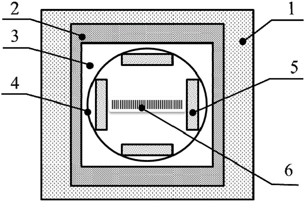
[0039] Step three, follow the attached figure 1 Load the prepared fluorescent layer into the four slots of the wheel device, fix and adjust it to an appropriate angle;
[0040] Step 4: Load a layer of plated radioactive metal nickel-63 and non-radioactive metal nickel on the center of the wheel device with a thickness of about 5μm;
[0041] Step 5. Prepare the InGaP / GaAs / Ge three-junction semi...
Embodiment 2
[0044] This example is the same as Example 1 except for the following differences.
[0045] Step 1. Select a colorless transparent epoxy resin with a viscosity of 4500~5500MPa·s at room temperature and a colorless transparent curing agent with a viscosity of 350~500MPa·s, and pre-treat the radiation-induced phosphors. Hot for a while
[0046] Step 2: Adhesive compounding technology is used to mix epoxy resin and curing agent at a weight ratio of 2:1, mix with 0.16g of ZnS:Cu radiation-induced phosphor, stir evenly, heat and solidify, remove corners and trim after cooling Into a suitable size to complete the preparation of the fluorescent layer;
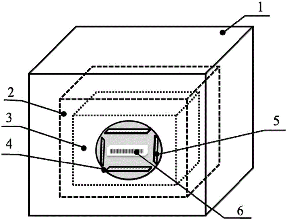
[0047] Step 6. Prepare the peripheral cladding device of the nuclear battery according to Figure 4 The structure of the battery is to nest each unit of the battery in the stainless steel material 1 in turn, and use screws and other connecting means to load a sealing cover above the entire peripheral structure to fix the entire device to co...
Embodiment 3
[0049] This example is the same as Example 1 except for the following differences.
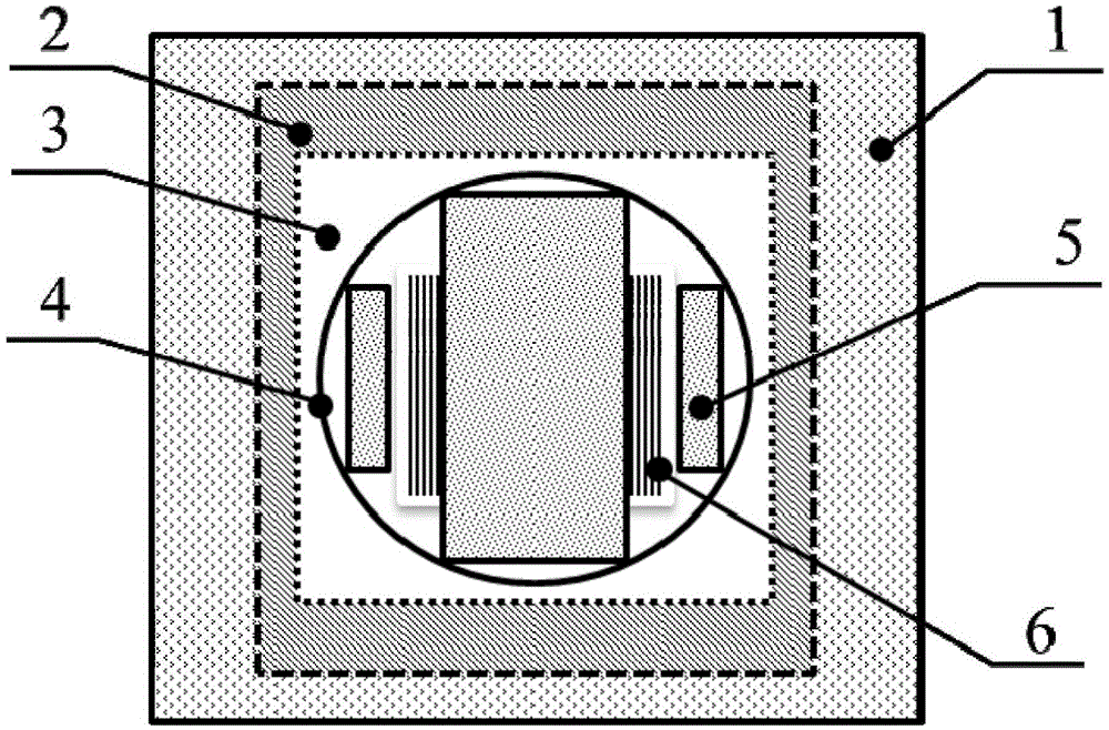
[0050] Step 2: Use physical sedimentation technology to deposit a layer of Y with a thickness of 91 μm on the quartz glass substrate 2 O 2 S: Eu fluorescent layer 5. Place the deposited sample at 250°C for 30 minutes to dry, and then take it out after it is naturally cooled to room temperature to complete the preparation of the fluorescent layer. The entire preparation environment is at normal pressure;
[0051] Step 4. Load a layer of plated radioactive metal promethium-147 and a cuboid source of non-radioactive metal promethium on the center of the runner device, the size is 30mm*30mm*100mm;
[0052] Step 6. Prepare the peripheral cladding device of the nuclear battery according to Figure 5 The structure of the battery is to nest each unit of the battery in the stainless steel material 1 in turn, and use screws and other connecting means to load a sealing cover above the entire peripheral structure...
PUM
 Abstract
Description
Claims
Application Information
 - R&D
- Intellectual Property
- Life Sciences
- Materials
- Tech Scout
- Unparalleled Data Quality
- Higher Quality Content
- 60% Fewer Hallucinations
Browse by: Latest US Patents, China's latest patents, Technical Efficacy Thesaurus, Application Domain, Technology Topic, Popular Technical Reports.
© 2025 PatSnap. All rights reserved.Legal|Privacy policy|Modern Slavery Act Transparency Statement|Sitemap|About US| Contact US: help@patsnap.com


