Semiconductor device and manufacturing method thereof
A manufacturing method and semiconductor technology, applied in the direction of semiconductor/solid-state device manufacturing, semiconductor devices, transistors, etc., can solve the problem of carrier mobility reduction, achieve low-cost manufacturing methods, stable and stable manufacturing methods, and improve on-resistance increased effect
- Summary
- Abstract
- Description
- Claims
- Application Information
AI Technical Summary
Problems solved by technology
Method used
Image
Examples
Embodiment 1
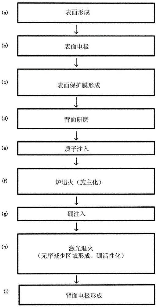
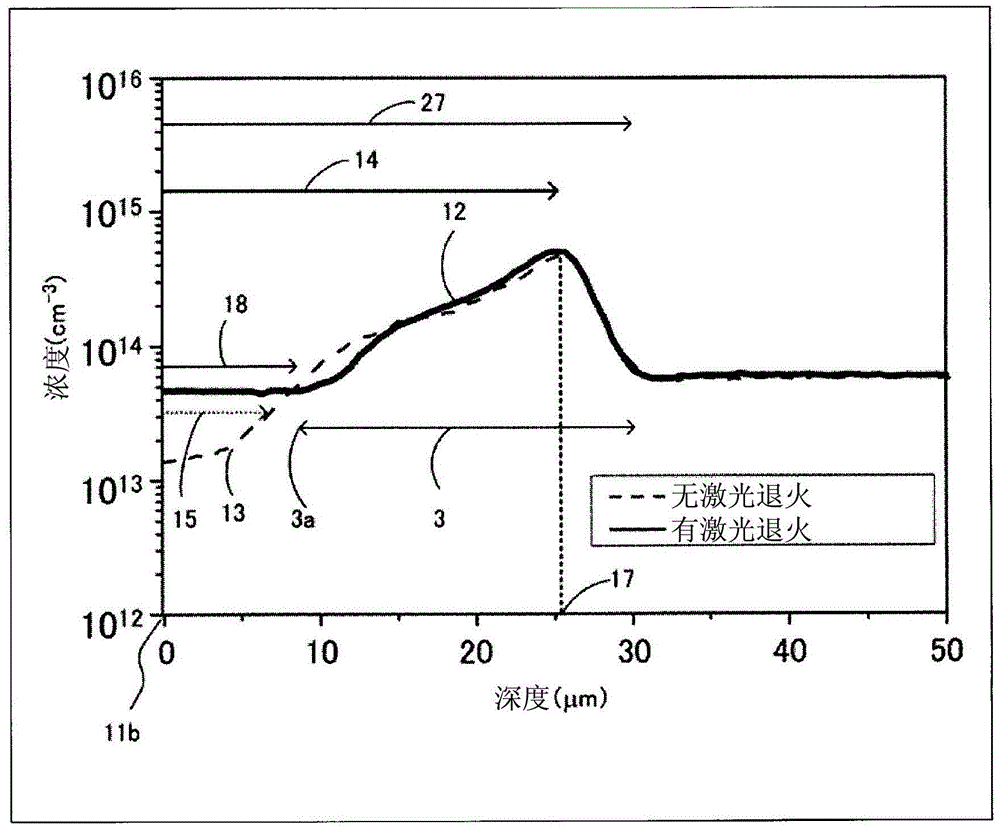
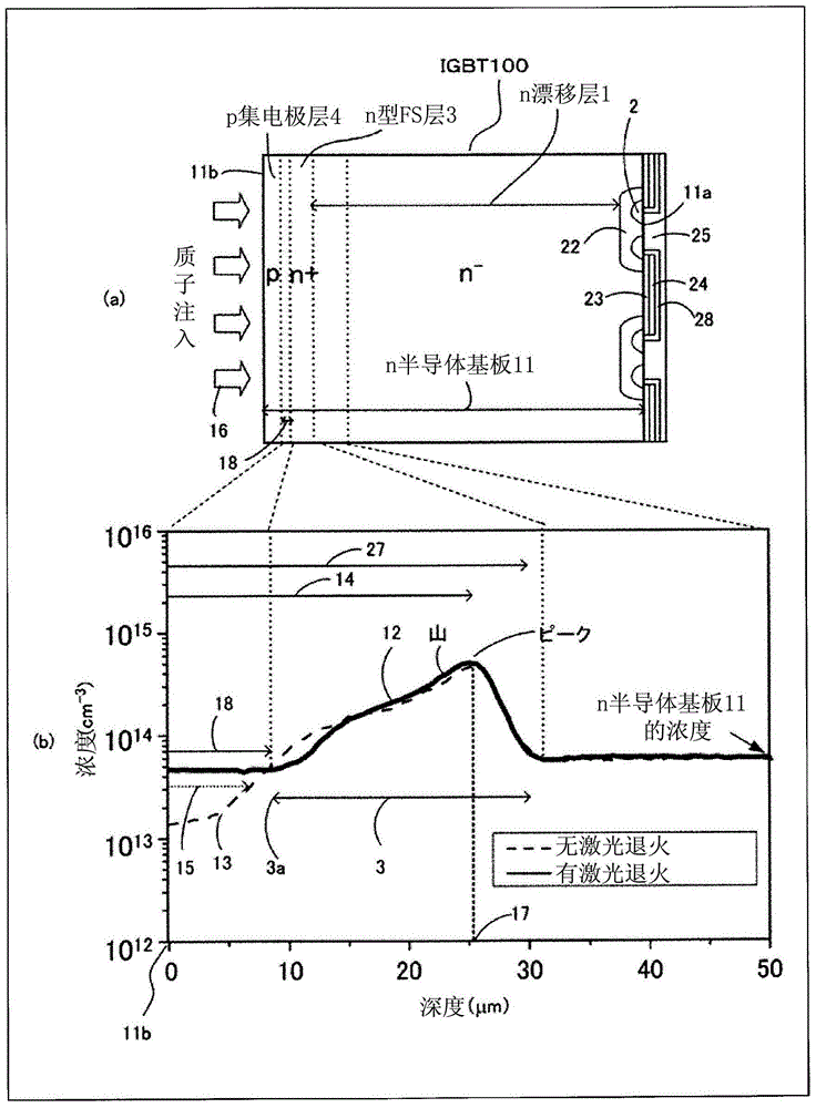
[0057] figure 1 It is a process flow chart showing the method of manufacturing the semiconductor device (IGBT 100 ) according to the first embodiment of the present invention. image 3 is used figure 1 The cross-sectional view (a) of the main part of the IGBT 100 produced in the process flow of the present invention and the graph of the carrier concentration curve (b) near the n-type electric field stop layer 3 . refer to figure 1 process flow and image 3 (a) is a cross-sectional view of main parts to describe the method of manufacturing the semiconductor device according to the first embodiment of the present invention.
[0058] First, in figure 1 In the surface forming step of (a), on one main surface (surface 11a) of n semiconductor substrate (wafer) 11, p base layer 22, n emitter layer 2, gate insulating film 23, gate electrode 24, and interlayer insulating film are formed. MOS gate structure composed of film 28 and so on. Wherein, the n-emitting layer 2 is form...
Embodiment 2
[0083] The semiconductor device of Example 2 will be described. Figure 4 It is a process flow diagram showing a method of manufacturing a semiconductor device according to Embodiment 2 of the present invention.
[0084] The difference from Example 1 is that after proton implantation, boron implantation ( Figure 4 (e) process), followed by laser annealing ( Figure 4 (f) process) and subsequent furnace annealing treatment ( Figure 4 (g) process). At this time, in the previous laser annealing process, the protons generated in the proton implantation 16 pass through the region 14 to form the n-type disorder-reducing region 18 while activating boron to form the p-collector layer 4 . In addition, in the furnace annealing treatment performed in the subsequent step, protons are donated to form the n-type field stop layer 3 . Also in this case, as in Example 1, by combining the laser annealing treatment and the furnace annealing treatment, the n-type disorder-reduced region 18 ...
Embodiment 3
[0088] The semiconductor device of the third embodiment will be described. In Example 3, one or more n-type intermediate layers 27 consisting of a pair of n-type field stop layer 3 and n-type disorder reducing region 18 are formed, for example, an IGBT in which three are formed as in this example. Figure 5 It is a cross-sectional view (a) of a main part of a semiconductor device (IGBT 100 ) according to Example 3 of the present invention and a graph of a carrier concentration curve (b) near the n-type field stop layer 3 . By forming a plurality of n-type intermediate layers 27 in this way, it is possible to relax the diffusion of the depletion layer at the time of turning off, and suppress the oscillation phenomenon at the time of switching (at the time of turning off).
PUM
| Property | Measurement | Unit |
|---|---|---|
| wavelength | aaaaa | aaaaa |
Abstract
Description
Claims
Application Information
 - R&D
- Intellectual Property
- Life Sciences
- Materials
- Tech Scout
- Unparalleled Data Quality
- Higher Quality Content
- 60% Fewer Hallucinations
Browse by: Latest US Patents, China's latest patents, Technical Efficacy Thesaurus, Application Domain, Technology Topic, Popular Technical Reports.
© 2025 PatSnap. All rights reserved.Legal|Privacy policy|Modern Slavery Act Transparency Statement|Sitemap|About US| Contact US: help@patsnap.com


