
Novel welding device

A welding device and a new type of technology, applied in the direction of electrode support device, electrode features, electrode accessories, etc., can solve problems such as poor conductivity, burn-through, welding wire melting, etc., to reduce welding wire consumption, improve welding quality, and achieve good results.

Active Publication Date: 2014-08-27
中冶辽宁德龙钢管有限公司
View PDF11 Cites 3 Cited by
  • Summary
  • Abstract
  • Description
  • Claims
  • Application Information

AI Technical Summary

Problems solved by technology

The disadvantages of existing welding torches are: 1. After a period of wear and tear, the gap between the welding wire and the welding torch head becomes larger, and the welding torch head needs to be replaced frequently. If the replacement is not timely, welding defects will occur in the weld, such as air holes, inclusions, etc.; 2. .The working environment where the welding torch head is located is relatively complicated. After a period of use, flux, dust, sludge and other debris will block the inner hole of the outer welding torch head, resulting in blocked wire feeding. When the resistance is too large, the welding wire will even be connected to the torch head in advance 3. The original welding torch head is in the shape of a hollow tube, and the welding wire is in a free state without external force constraints. When the welding wire is partially bent, poor conductivity often occurs, increasing the resistance of the wire feeding, and welding will occur. Welding defects such as sparking and burn-through

Method used


Image

  • Novel welding device
  • Novel welding device

Examples


Embodiment Construction

[0019] The specific embodiment of the present invention will be further described below in conjunction with accompanying drawing:

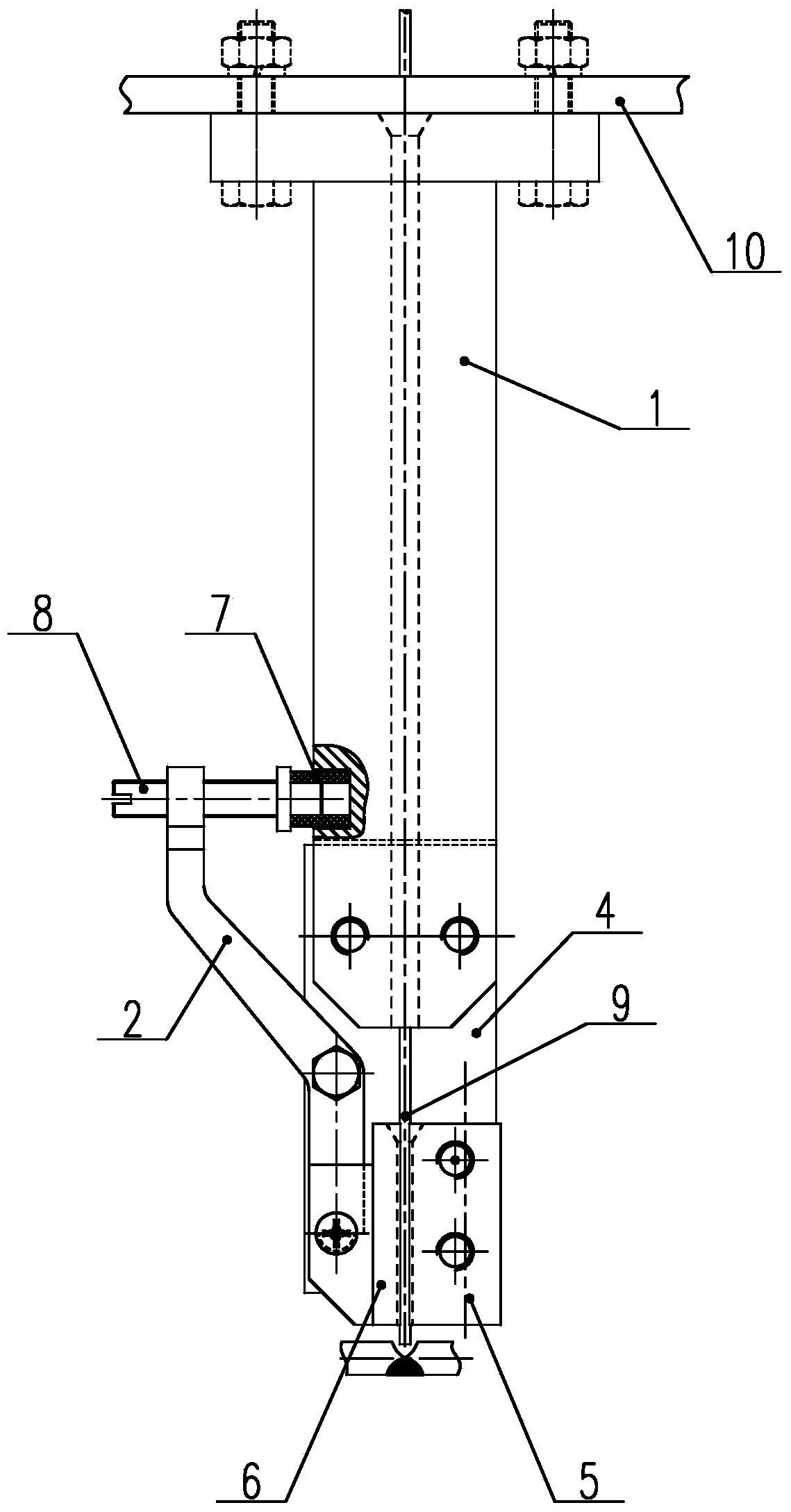
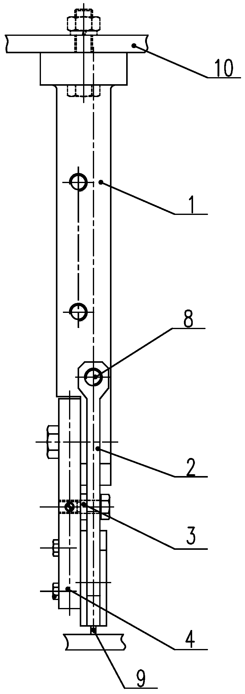
[0020] See Figure 1-Figure 2 , is a structural schematic diagram of the present invention, a new welding device of the present invention, including a conductive rod 1, a connecting rod 2, a conductive plate 4, a welding head 5 and a welding head 2 6, and the conductive plate 4 is fixed on the conductive rod 1 , the two ends of the connecting rod 2 are respectively connected with the conductive rod 1 and the conductive plate 4, the welding head 5 is fixed on the conductive plate 4, the welding head 2 6 is fixed on the connecting rod 2, and the welding head 5 and the welding head 2 6 A slit through which the welding wire 9 passes is formed.

[0021] The conductive rod 1 and the conductive plate 4 are connected by bolts, and the middle part of the connecting rod 2 is fixed on the conductive plate 4 by bolts, and is locked with screws; between the w...


PUM


Abstract

The invention relates to a novel welding device. The novel welding device comprises a conducting rod, a connecting rod, a conducting plate, a first welding head and a second welding head; the conducting plate is fixed to the conducting rod; two ends of the connecting rods are respectively connected with the conducting rod and the conducting plate; the first welding head is fixed to the conducting plate, and while the second welding head is fixed to the connecting rod; a gap through which a welding wire passes is formed between the first welding head and the second welding head; the connecting rod and the conducting rod are connected through an adjusting bolt; one end of the adjusting bolt, provided with threads, is sleeved with the connecting rod; one end of a straight pin is fixed to the conducting rod through an insulating sleeve. Compared with the prior art, the novel welding device has the beneficial effects that 1) the connecting rod arranged enables separated arrangement of the welding heads, thus the gap at the part in which the welding wire is clamped at the head part of a welding gun can be automatically fine adjusted, the welding wire can pass through smoothly, and a continuous clamping force is provided for the welding wire; 2) the wear can be automatically compensated, foreign matters on the welding wire can be removed, and thereby high conductivity is ensured; 3) the structure is simple, the use effect is great, the welding quality can be effectively improved, and the consumption of welding wire can be reduced.

Description

technical field [0001] The invention relates to a welding device, in particular to a new welding device capable of automatically adjusting the wire feeding gap. Background technique [0002] The welding torch uses the high current of the welding machine, and the heat generated by the high voltage gathers at the terminal of the welding torch, melts the welding wire, and the melted welding wire penetrates into the part to be welded. After cooling, the welded object is firmly connected into one. With the improvement of technological level and product equipment manufacturing technology, the requirements for welding quality and welding process are getting higher and higher. The disadvantages of existing welding torches are: 1. After a period of wear and tear, the gap between the welding wire and the welding torch head becomes larger, and the welding torch head needs to be replaced frequently. If the replacement is not timely, welding defects will occur in the weld, such as air ho...

Claims


Application Information

Patent Timeline
Patent Type & Authority Applications(China)
IPC IPC(8): B23K9/26B23K9/28
CPCB23K9/26B23K9/28
Inventor 赵旭薛俊
Owner 中冶辽宁德龙钢管有限公司
Learn More