Non-penetration laser welding apparatus and non-penetration laser welding method

A laser welding, laser welding head technology, applied in laser welding equipment, welding equipment, metal processing equipment and other directions, can solve the problems of ineffective prevention and adjustment, no development, high flexibility, and achieve strong adaptability and deep penetration , the effect of strong anti-interference ability

Inactive Publication Date: 2014-08-27
HUNAN UNIV
View PDF11 Cites 37 Cited by
  • Summary
  • Abstract
  • Description
  • Claims
  • Application Information

AI Technical Summary

Problems solved by technology

[0014] Although the theoretical research of the above experimental methods has achieved certain results, they are all limited to identifying whether the molten pool is penetrated during the welding process. There is still a big gap in the application of the non-penetration welding monitoring in industrial production, and none of them have been developed. A non-penetration welding equipment with high efficiency, precision, real-time control and high flexibility
[0015] German scholar F.Abt uses a closed-circuit control system based on a cellular neural network camera (CNN camera) to analyze the image features of the Yb:YAG laser lap welding process, and collects the image features of small welding holes coaxially in real time. Comparing and analyzing the images of the small holes in the cases of only the penetration of the upper plate and the full penetration of the upper and lower plates, and then feedback and adjusting the laser power to control the welding process in real time, achieving good results and realizing lap joints Real-time monitoring of non-penetration, but it cannot effectively prevent and adjust defects such as back burns in the non-penetration state

Method used


Image

  • Non-penetration laser welding apparatus and non-penetration laser welding method
  • Non-penetration laser welding apparatus and non-penetration laser welding method
  • Non-penetration laser welding apparatus and non-penetration laser welding method

Examples


Embodiment Construction

[0041] The following will be combined with the attached Figure 1-4 Specific embodiments of the present invention will be described in detail.

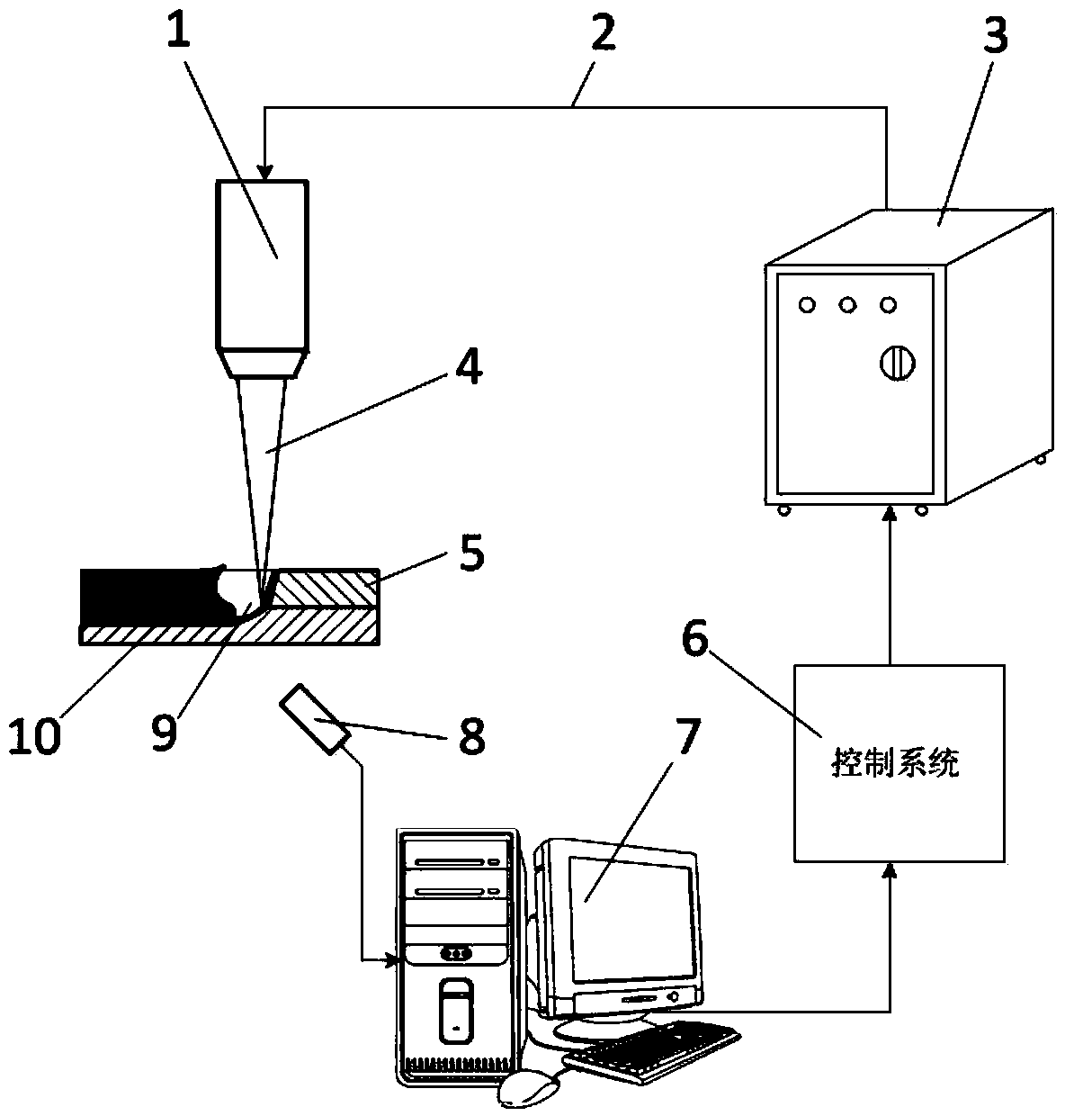
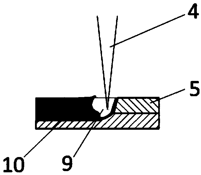
[0042] like figure 1 As shown, a non-penetrating laser welding equipment includes: a laser welding head 1, a transmission fiber 2, a laser 3, a feedback control system 6, a computer 7, and an infrared temperature acquisition system 8, which is characterized in that: the laser output by the laser 3, Conducted to the laser welding head 1 through the optical fiber 2, the laser beam 4 focused by the focusing lens inside the welding head acts on the surface of the welding material 5 to weld the material, and the infrared temperature acquisition system 8 captures the temperature of the back of the weld seam online during the welding process. And the acquired information is transmitted to the computer 7 in real time, and the computer 7 analyzes and processes the received information to obtain the welding penetration situation of the materia...


PUM

PropertyMeasurementUnit
thicknessaaaaaaaaaa

Abstract

The invention relates to a non-penetration laser welding apparatus. The non-penetration laser welding apparatus comprises a laser welding head (1), a transmitting optical fiber (2), a laser (3), a feedback control system (6), a computer (7) and an infrared temperature acquisition system (8); the non-penetration laser welding apparatus is characterized in that the laser light output by the laser (3) is transmitted to the laser welding head (1) by virtue of the optical fiber (2), a laser beam (4) focused by a focusing lens in the welding head acts on the surface of a welding material (5) to weld the material, the infrared temperature acquisition system (8) is used for capturing the temperature of the back surface of a weld joint in the welding process online, obtaining the present welding penetration condition of the material and transferring control information to the feedback control system (6), and the feedback control system (6) is used for controlling the laser (3) to adjust the power of the laser light in real time. The non-penetration laser welding apparatus is capable of performing accurate control on non-penetration welding adopted in industries so that the welded joint can be protected against non-fusion and back burn; the non-penetration laser welding apparatus is high in practicability.

Description

field of invention [0001] The invention relates to a laser welding device and method, in particular to a non-penetrating laser welding device and method. Background technique [0002] Laser welding is to radiate a high-intensity laser beam to the surface of the material. Through the interaction between the laser and the material, the material absorbs the laser energy and converts it into heat energy to make the material melt and then cool and crystallize to form welding. There are two basic methods of laser welding: heat conduction welding ( Also known as conduction welding, Heat Conduction Welding) and deep penetration welding (Deep Penetration Welding). The energy coupling mechanism, weld formation mechanism and welding effect of these two welding modes are completely different. [0003] (1) heat conduction welding [0004] When the laser power density is low (power density I<10 4 W / cm 2 ), the laser is irradiated on the surface of the material, except part of the l...

Claims


Application Information

Patent Timeline
Patent Type & Authority Applications(China)
IPC IPC(8): B23K26/21B23K26/062
CPCB23K26/034B23K26/14B23K26/24
Inventor 陈根余黎长邹周聪李时春张焱夏海龙陈晓峰廖生慧周逸凡
Owner HUNAN UNIV
Why Eureka
Try Eureka