Energy saving and efficiency improving method for plunger pump

A plunger pump, connected to the technology, applied in the pump, pump control, liquid variable capacity machinery and other directions, can solve the problems of low energy efficiency and mechanical efficiency, comprehensive work efficiency reduction, large mechanical loss, etc., to achieve shortened production cycle, The effect of reducing the difficulty of product maintenance and reducing production costs

Active Publication Date: 2014-08-27
NANTONG MUTE BUILDING TECH CO LTD
View PDF7 Cites 1 Cited by
  • Summary
  • Abstract
  • Description
  • Claims
  • Application Information

AI Technical Summary

Problems solved by technology

In addition to a large amount of energy loss, these two processes also have greater mechanical loss, resulting in very low energy efficiency and mechanical efficiency, coupled with leakage caused by complex structures, the overall work efficiency is greatly reduced

Method used


Image

  • Energy saving and efficiency improving method for plunger pump
  • Energy saving and efficiency improving method for plunger pump
  • Energy saving and efficiency improving method for plunger pump

Examples


Embodiment Construction

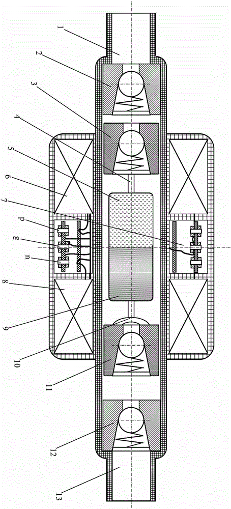
[0018] exist figure 1 In the illustrated embodiment of the invention—a linear drive plunger pump sectional view:

[0019] From left to right, the pump body of the linear drive plunger pump is divided into suction end, suction section, middle section, discharge section and discharge end. In the pump body, the suction section, the middle section, and the discharge section space between the suction valve 2 and the discharge valve 12 form a cylindrical piston cylinder; the suction end valve 3, the permanent magnet N pole 5, the permanent magnet S pole 9 and the discharge end valve 11 pass through The connecting structure of the connecting rod 4 and the connecting frame 10 constitutes a cylindrical piston. The piston is driven by the drive circuit through the N pole electromagnetic coil 6 and the S pole electromagnetic coil 8 .

[0020] Suction port 1, as the gas and liquid suction port and the installation end matched with the suction pipe, is located at the suction end of the p...


PUM


Abstract

The invention relates to an energy saving and efficiency improving method for a plunger pump. The plunger pump adopts a linear piston reciprocating and direct electromagnetic driving mode for operation and employs a control box for controlling. An N-pole electromagnetic coil homonymic terminal, an electromagnetic coil ground terminal and an electromagnetic coil synonymic terminal are connected with corresponding terminals in the control box through a driving power cathode wire, a power ground wire and a driving power cathode wire respectively. A cylindrical piston cylinder is formed in spaces of a suction section, an intermediate section and a discharge section, between a suction-port valve and a discharge-port valve, of an inner cavity of a pump body. A suction-terminal valve, a permanent magnet N-pole terminal, a permanent magnet S-pole terminal and a discharge-terminal valve form a cylindrical piston through a linkage structure of a connecting rod and a connection frame; the piston is driven by a driving circuit through an N-pole electromagnetic coil and an S-pole electromagnetic coil. The driving circuit of the plunger pump includes driving signal generation, conversion and amplification and switch execution.

Description

technical field [0001] The invention relates to a system structure design and a driving operation method of a plunger pump. Background technique [0002] Many pumps, especially plunger pumps, have become widely used products due to their advantages such as small leakage and high pressure. The plunger pump is driven by a rotating motor to drive a rotating machine, and then the rotating machine drives a cylindrical piston to run. It converts electrical energy into rotational mechanical energy first, and then converts rotational mechanical energy into linear motion mechanical energy. In addition to a large amount of energy loss, these two processes also have greater mechanical loss, resulting in very low energy efficiency and mechanical efficiency. In addition to the leakage caused by the complex structure, the overall work efficiency is greatly reduced. And its use in a wide range of fields will inevitably produce immeasurable energy-saving and efficiency-enhancing issues su...

Claims


Application Information

Patent Timeline
Patent Type & Authority Applications(China)
IPC IPC(8): F04B17/04F04B49/06
Inventor 屈百达
Owner NANTONG MUTE BUILDING TECH CO LTD
Why Eureka
Try Eureka