Large-tonnage lifting mechanism for trackless forging manipulator

A forging manipulator, large tonnage technology, applied in forging/pressing/hammering machinery, manufacturing tools, forging/pressing/hammer devices, etc. The clamp is difficult to lift horizontally, etc., to achieve the effect of high practical value, strong movement reliability and simple structure

Inactive Publication Date: 2014-09-03
YANSHAN UNIV
View PDF9 Cites 3 Cited by
  • Summary
  • Abstract
  • Description
  • Claims
  • Application Information

AI Technical Summary

Problems solved by technology

After searching, it was found that the existing trackless forging manipulators transformed from forklifts, loaders, and loaders had poor rigidity and small carrying capacity
The Chinese patent with the publication number CN2476368Y discloses a trackless forging manipulator, which adopts the synchronous movement of the front and rear electric hoists to make the clamps move up or down, with poor synchronization, poor stability of the steel wire rope suspension structure, and small bearing capacity
The British patent with the publication number UK GB1333299 discloses a trackless forging manipulator. When it is lifted, it is difficult to keep the clamps up and down horizontally, and the structure is complicated and the load capacity is small.
The Chinese patent with the publication number CN 102728764A discloses a parallel link type forging manipulator lifting mechanism, which improves the carrying capacity of the forging manipulator. On the ground, not suitable for trackless forging manipulators

Method used


Image

  • Large-tonnage lifting mechanism for trackless forging manipulator

Examples


Embodiment Construction

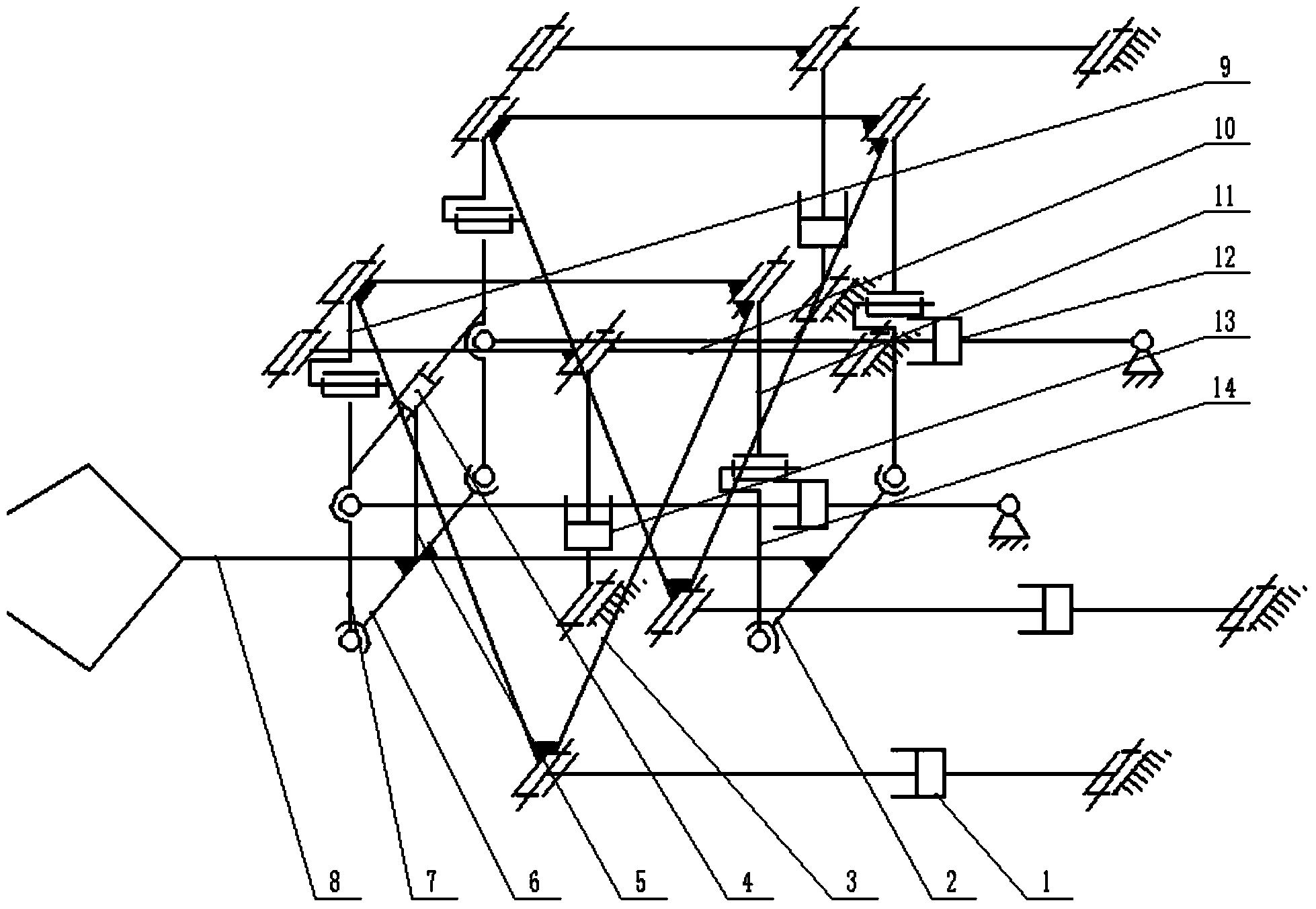
[0015] exist figure 1 In the schematic diagram of the hoisting mechanism of the large tonnage trackless forging manipulator shown, the front part of the clamp main shaft 8 is fixedly connected to the front cross bar 6, the rear end of the clamp main shaft is fixedly connected to the rear cross bar 2, and the two front cross bar The ends are respectively connected to one end of a pair of front connecting rods 7 through a ball hinge, and the other ends of the pair of front connecting rods are respectively hinged with one end of a pair of front suspension rods 9 through a rotating hinge. The ball hinge is connected with one end of a pair of rear connecting rods 14, and the other ends of the pair of rear connecting rods are respectively hinged with one end of a pair of rear suspension rods 11 through a rotating hinge, and the left and right horizontal buffer cylinders 4 are fixedly connected by the buffer cylinder connecting rods 5 At the position where the front part of the main ...


PUM


Abstract

The invention discloses a large-tonnage lifting mechanism for a trackless forging manipulator. The front portion and the rear portion of a main clamp shaft are fixedly connected with a front cross bar and a rear cross bar respectively, the two ends of a front connection bar are hinged to the front cross bar and a front hanging bar, and the two ends of a rear connection bar are hinged to the rear cross bar and a rear hanging bar. A left-to-right horizontal buffering cylinder is fixedly connected to the front portion of the main clamp shaft, and the two ends of the left-to-right horizontal buffering cylinder abut against the front hanging bar. The other end of the front hanging bar and the other end of the rear hanging bar are connected with the front endpoints and the rear endpoints of a pair of triangular frames, and inclined cylinders are connected with the lower endpoints of the triangular frames and a machine frame. Upper connection bars are connected with the front endpoints of the triangular frames and the machine frame. A front-to-back horizontal buffering cylinder is connected with the front hanging bar and the machine frame. Lifting cylinders are hinged to the middle portions of the upper connection bars and the machine frame. The large-tonnage lifting mechanism is symmetrically distributed with the main clamp shaft as the center and is simple in structure, good in synchronism and high in bearing capacity, the lifting motion trail of a clamp is close to a straight line, the position accuracy is high, and the view of a driver control console is wide.

Description

technical field [0001] The invention relates to forging operation equipment, in particular to a trackless forging operation machine. Background technique [0002] The forging manipulator is one of the important equipments in the forging workshop to realize forging mechanization and automation. It is used in conjunction with the forging hydraulic press to improve the quality of forgings and production efficiency. At present, forging manipulators are divided into trackless forging manipulators and rail forging manipulators. The rail forging manipulator is installed next to the forging hydraulic press, and the range of activities and the forging equipment it serves are determined. The trackless forging manipulator has a wide range of activities and good mobility, and can serve multiple forging equipment. The driver's console is set on the forging manipulator, which can not only operate forgings, but also serve as the transportation work of the forging workshop. After searchin...

Claims


Application Information

Patent Timeline
Patent Type & Authority Applications(China)
IPC IPC(8): B21J13/10
Inventor 翟富刚韩浩然冯伟孔祥东
Owner YANSHAN UNIV
Why Eureka
Try Eureka